Insert North Sign or Directional Arrow
SDBox Design Software - Command guide for inserting and managing north signs, directional arrows, and symbol libraries in CAD drawings
North Sign / Arrow Insertion ZBOR
Insert a North sign or directional arrow Block from a library into the drawing area, with size automatically scaled according to the print scale.
This command opens a selection dialog (tab) where you can choose from a library of pre-defined north signs and directional arrows. The selected symbol is inserted into your drawing at a size that will be clearly visible when printed, based on the current plot scale.
Enter LAYER for 'North Sign - Arrow':
Steps
- Run the command ZBOR.
- Specify the Layer for the inserted symbol.
- A dialog opens, displaying available symbols (Blocks) and their previews (Slides).
- Select the desired symbol from the list or by clicking its preview image.
- You are prompted to pick an insertion point in the drawing.
- Specify a rotation angle or press Enter for horizontal (0 degrees).
- After insertion, you can choose to insert another instance, change the symbol, mirror it, or finish.
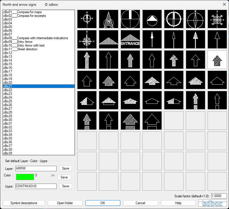
ZBOR command selection dialog with symbol list and previews
<...if you pick a point ENTER=angle 0.0000>
Select a point in the drawing for the symbol's insertion. Then either pick a second point to define the rotation angle or type an angle value. Pressing Enter, Space, or right-clicking accepts the default angle of 0 degrees (horizontal).
Next "Entrance Arrow (zBo09)" ? R/S/U/Y/N <Yes> :
After inserting a symbol, you are presented with options to continue inserting more symbols.
Post-Insertion Options
- R (Reverse direction): Mirrors the Block along its insertion axis without affecting text readability. Useful for linear symbols to fit clean areas of the drawing.
- S (Change Symbol): Re-opens the symbol selection dialog to choose a different Block.
- Y (Yes/Continue): Continues inserting another instance of the current symbol.
- N (No/End): Ends the command and reports how many symbols were inserted.
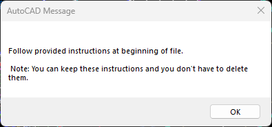
"Symbol Descriptions" button in the ZBOR dialog
Symbol Library Management
The symbols are stored as drawing files (.dwg) and their preview images as Slide files (.sld) in the folder \\SDBOX\SBL_zBO.
- You can enrich the library with your own symbols.
- Symbol files must be named sequentially: zBo01.dwg to zBo63.dwg.
- For each
.dwgfile, a corresponding Slide file with the same name must be created (using AutoCAD'sMSLIDEcommand) for previews to appear in the dialog. - When creating a new symbol Block, use the AutoCAD
BASEcommand to define its insertion point.
Notes:
When creating a new Drawing - symbol, also set its insertion point using the AutoCAD base command.
The folder \\SDBOX\SBL_zBO can contain a maximum of 63 Drawings (in consecutive numerical order). Drawings beyond this number are not included in the command.
For each drawing, create the corresponding slide with the same name using the AutoCAD mslide command.
You can also open the description file using the ZBOR1 command.
You can also open a file listing all participating Blocks using the ZBORLIST command.
You can also open the symbols folder using the ZBORDIR command.
Command Usage:
The command's ability to save the values you enter for the Block's attributes (Layer, etc.) and suggest them for the next Block is useful when you want to insert multiple Blocks with the same attribute values, allowing for changes each time if needed.
The symbol descriptions displayed in the command's dialog help you distinguish between visually similar Blocks.
Tips:
The selections you make each time you run the command are saved and suggested thereafter, both in the same drawing and in any other drawing.
If you agree with the suggested values (the last used ones) when the dialog opens, you can press Enter or Space to accept them and proceed directly to inserting the symbol in the drawing area.
Symbol Descriptions ZBOR1
Opens the file containing the descriptions for the North Sign or Arrow symbols that are inserted into the Drawing with the ZBOR command.
This command opens the file \\SDBOX\ZBOR.dat where you can view, edit, or add new descriptions. These descriptions appear in the left-hand list of the ZBOR command dialog, helping you identify symbols.
File Creation / Editing
Running the command opens the description file in your default text editor. If the file does not exist, it will be created.
Each line in the description file follows this format:
SymbolFileName ? Description Text
For example, to add the description "Entrance Arrow" for the symbol file zBo09.dwg, add the following line:
zBo09 ? Entrance Arrow
This will appear in the ZBOR dialog list as: zBo09_Entrance Arrow.
Reminder message about instructional text in the file header
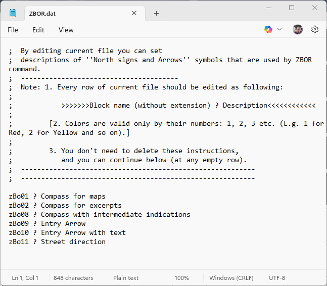
Example of the ZBOR.dat description file
Notes:
You can copy the list of symbols using the ZBORLIST command into the description file. Then, by deleting the .dwg extensions, you can complete the descriptions.
You can open the folder containing the symbols with the ZBORDIR command.
Command Usage:
The symbol descriptions displayed in the ZBOR command dialog help you distinguish between visually similar Blocks.
The ZBOR1 command can also be executed from within the ZBOR dialog by pressing the "Symbol Descriptions" button.
Tips:
It is recommended to add descriptions for all Blocks that participate in the ZBOR command. This gives you a complete overview and makes it easy to insert the desired Block each time.
Symbol List with Icons ZBORLIST
Opens a file containing a list with the names of all North Sign or Arrow symbol drawings (Blocks) that are available for insertion with the ZBOR command.
This command opens the file \\SDBOX\SBL_zBO_LIST.dat. This file lists all Drawing files (Block definitions) that exist in the \\SDBOX\SBL_zBO folder and are available for use with the ZBOR command.
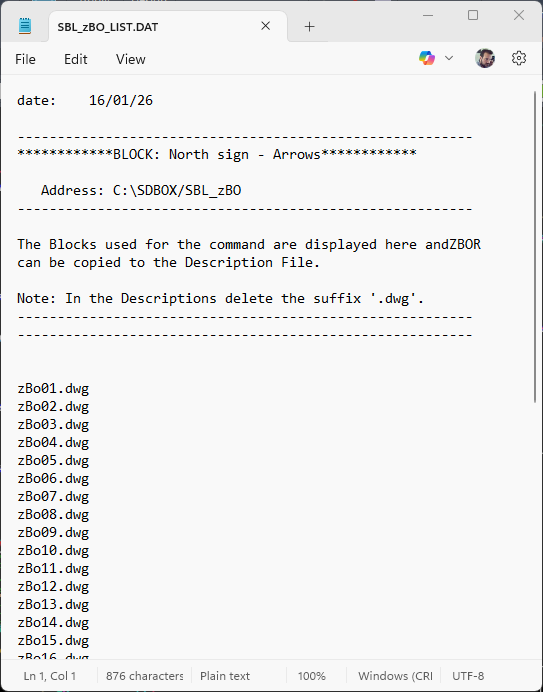
Example output of the ZBORLIST command
Notes:
Every time you run the command in any drawing, it always opens the same file at \\SDBOX\SBL_zBO_LIST.dat.
If you wish, you can save this file under a different name or in a different location for your own use.
Command Usage:
The file that opens lists all the Drawing files (Blocks) in the \\SDBOX\SBL_zBO folder that participate in the ZBOR command. It is not used as an input file by any command.
It opens so you can have an overview of the available Blocks, or to copy the Block names (typically to paste them into the symbol description file and complete the descriptions).
Tips:
You can run the ZBORLIST command first, leave the file open, and then run the ZBOR1 command. With both files open, you can easily copy and paste the symbol names to complete the descriptions.
You can open the folder containing the symbols with the ZBORDIR command.
Open Symbols Folder ZBORDIR
Opens (via Windows Explorer) the folder containing the drawing files and slide files for the North Sign or Arrow symbols used by the ZBOR command.
This command opens the folder \\SDBOX\SBL_zBO. This folder contains the actual symbol drawing files (.dwg) and their corresponding preview slide files (.sld) that are displayed in the ZBOR command dialog.
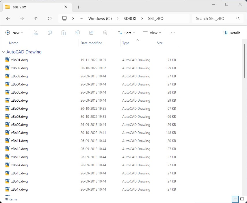
Contents of the SBL_zBO symbols folder
Folder Management
You can create new symbols or rename existing ones directly in this folder.
- When renaming a Drawing file, also rename its corresponding Slide file.
- When creating a new Drawing, you must also create its corresponding Slide using the AutoCAD
MSLIDEcommand. - Symbol file names must follow the pattern: zBo01 to zBo63 (in consecutive numerical order).
- When creating a new symbol Block, use the AutoCAD
BASEcommand to define its insertion point.
Notes:
You cannot move this folder to a different location, because the ZBOR command reads only from the specific path \\SDBOX\SBL_zBO.
Command Usage:
Use this command to directly manage the source symbol files: add new ones, delete unused ones, or update existing symbols.
Tips:
The folder \\SDBOX\SBL_zBO can contain a maximum of 63 Drawings (in consecutive numerical order). Drawings beyond this number are not included in the command.