Floor Level Markers
SDBox Design Software - Command guide for inserting floor level and height markers with calculation capabilities
Introduction to Floor Level Markers
The ZST command is a comprehensive solution for managing floor levels and heights in architectural CAD drawings.
This powerful add-on for AutoCAD and compatible CAD systems provides intelligent block insertion with automatic value tracking per category, ensuring consistency across complex architectural projects. The system remembers your previously entered values for each level type and suggests them in subsequent uses, dramatically improving workflow efficiency.
Whether you're working on residential buildings, commercial complexes, or industrial facilities, ZST streamlines the process of marking floor levels, ceiling heights, slab elevations, and other critical vertical dimensions.
Key Benefits:
- Automatic value tracking by category (levels, heights, slabs, etc.)
- Scale-aware block insertion for optimal print quality
- Extensible symbol library with custom block support
- Built-in calculation capabilities for height differences and operations
- Consistent formatting across all level markers in a project
Typical Applications:
- Architectural floor plans with multiple level changes
- Interior design documentation with ceiling height variations
- Structural drawings with slab and beam elevations
- Facility management documentation
- Building renovation projects with existing level surveys
Insert Floor Level/Height with Calculations ZST
Inserting floor level or height markers into the drawing, with organization and retrieval of values by category, calculation capabilities, number selection from the screen, etc.
Selection from a library for inserting a Block with size proportional to the print scale.
Enter Layer for "Levels":
Main Features
- Category-based value management: Values are stored and suggested per field type
- Scale-aware insertion: Blocks automatically scale for optimal print quality
- Calculation capabilities: Built-in calculator for height differences and operations
- Screen selection: Pick values directly from existing text in the drawing
- Extensible library: Add your own custom symbols and descriptions
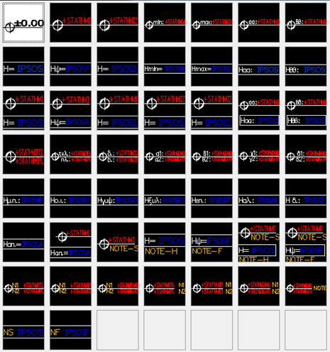
Overview of available level marker symbols
E/D/P/!/!! Enter number Level ? <0.20> :
Input Options During Command Execution
- Enter: Accept suggested value (e.g., 0.20)
- Type a number: Enter specific value
- E: Select a number from existing text or block in the drawing
- D: Calculate height difference by selecting floor and ceiling levels
- P: Perform mathematical operations with selected numbers
- ! or !!: Select Z coordinate of object or point with linear interpolation
Workflow Tip:
The command's ability to remember previously entered values for each field type means you can quickly insert multiple level markers with consistent values. When working on a project with standardized floor-to-floor heights, this feature saves significant time.
Symbol Reference Guide
ZST includes a comprehensive library of level and height markers organized by category:
Basic Level Markers
zSt01: Inserted as is (no value prompt)
zSt02: General Room Level
Field: +STATHMI
zSt03: General Level 2
Field: +STATHMI2
Height Markers
zSt08: Room Height (floor to ceiling)
Field: IPSOS
zSt09: Height to False Ceiling
Field: IPSOSF
zSt10: General Height 2
Field: IPSOS2
Combined Markers
zSt15: Level and Room Height
Fields: +STATHMI, IPSOS
zSt16: Level and Height to False Ceiling
Fields: +STATHMI, IPSOSF
zSt17: Level and Height 2
Fields: +STATHMI, IPSOS2
Construction Markers
zSt22: Slab - Final Floor
Fields: +STATHMITEL, +STATHMPL
zSt24: Floor - Concrete
Fields: +STATHMID, +STATHMIB
zSt25-28: Upper - Lower Levels
Fields: +STATHMIANO, +STATHMIKATO
Naming Convention:
Fields starting with +STATHMI are for levels (positive numbers get + sign). Fields starting with IPSOS are for heights (no sign added). This allows easy selection of all level or height fields using wildcards like +STATHMI* in other commands.
Insert Level Block ZSTA
Opens a tab showing available Blocks (with their descriptions) located at \\SDBOX\SBL\zStathmes
You can modify existing blocks or create new ones in this location. When creating new blocks, name them zSt01.dwg to zSt63.dwg (in continuous numerical sequence) and create corresponding slides with the same name to display in the right panel of the tab.
Block list
Creating Custom Blocks
- Create your block drawing in AutoCAD
- Name it zSt01.dwg to zSt63.dwg (next available number)
- Use MSLIDE command to create slide file with same name
- Place both files in \\SDBOX\SBL\zStathmes folder
- Run ZSTA command to verify appearance
+STATHMI (general level)
+STATHMI2 (general level 2)
+STATHMIPL (slab level)
// For height fields use:
IPSOS (height to ceiling)
IPSOSF (height to false ceiling)
IPSOS2 (general height 2)
Symbol Descriptions ZST1
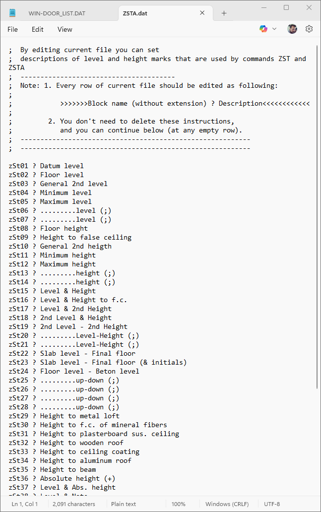
Opens the file \\SDBOX\ZSTA.dat containing symbol descriptions displayed in the left list of the tab.
Edit this file to add or modify descriptions for symbols. Each line should follow the format: "zSt16 ? Level-Height to false ceiling"
This will appear in the tab list as: "zSt16__Level-Height to false ceiling"
Editing symbol descriptions
Description Tips:
Descriptions should clearly indicate the block's purpose. Use consistent terminology across similar blocks. Descriptions are for your reference only and don't affect block functionality.
Symbol List ZSTLIST
Opens a tab showing all available blocks with their descriptions.
This provides a comprehensive overview of all level marker symbols in your library, helping you choose the appropriate block for each situation.
Usage:
Use ZSTLIST when you need to browse all available symbols or when setting up a new project to ensure you have all required markers.
Open Folder ZSTDIR
Ends the command (no symbol inserted) and opens the folder containing the drawing symbols (*.dwg) and corresponding slides.
You can rename existing drawings or create new ones. When renaming, also rename the corresponding slide file. When creating new drawings, create corresponding slides using AutoCAD's MSLIDE command.
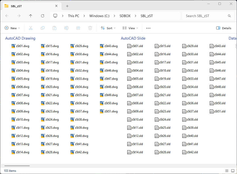
Symbols and slides folder structure
Naming: zSt01.dwg to zSt63.dwg
Slides: zSt01.sld to zSt63.sld
Advanced Features & Customization
Creating Custom Blocks
You can create your own level marker blocks with specific attributes:
+STATHMI : general level
+STATHMI2 : general level 2
+STATHMIPL : floor slab level
+STATHMITEL : final floor level
+STATHMIB : concrete level
+STATHMID : floor level
+STATHMIANO : general upper level
+STATHMIKATO : general lower level
// Height attribute names:
IPSOS : height to ceiling
IPSOS2 : general height 2
IPSOSF : height to false ceiling
IPSOSM : minimum height
IPSOSX : maximum height
IPSOSA : absolute height
IPSOSMP : height to metal ceiling
IPSOSOI : height to mineral fiber ceiling
IPSOSG : height to gypsum board ceiling
IPSOSKS : height to wooden ceiling
IPSOSEP : height to plastered ceiling
IPSOSAL : height to aluminum ceiling
IPSOSD : height to beam
Notes with Custom Text
Blocks zSt38-zSt51 include fields for notes (attributes: NOTE.., N1, etc.). These values are also stored and suggested in subsequent uses.
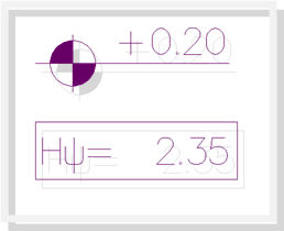
Level marker with additional note fields
Best Practices:
- Use consistent base points for all blocks
- Maintain similar text heights for readability
- Test blocks at various scales before production use
- Document custom blocks in your office standards
- Regularly back up your custom symbol library
Project Setup:
For new projects, set up your standard level markers first. Enter typical values once, and ZST will remember them throughout the project. This ensures consistency across all drawings and team members.