Drawing Options for Lines and Polylines
SDBox Design Software - Advanced drawing tools during Line, Polyline and Block commands in CAD
Introduction
Enhanced drawing capabilities during Line and Polyline commands with SDBox software.
While drawing Lines or Polylines, or inserting Blocks to scale, you have significantly more options than the standard AutoCAD commands. The following example demonstrates drawing a Line or Polyline as these commands contain the complete set of available options.
Compatibility:
These enhanced drawing options are available in AutoCAD 2010-20xx, BricsCAD, GstarCAD, and ZwCAD when using the SDBox add-on software.
The SDBox software extends the standard CAD functionality by providing additional geometric construction tools, point creation methods, and drawing aids that streamline the design process.
^ Back to topDrawing Options Overview
During Line, Polyline drawing or Block insertion at scale, you have numerous additional options beyond standard AutoCAD commands.
The SDBox add-on provides enhanced functionality that integrates seamlessly with your CAD workflow. The options appear in the command line during drawing operations, offering you extended capabilities without interrupting your design process.
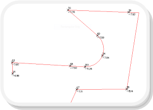
Drawing interface with extended options
Key Benefits:
- Integrated tools without switching commands
- Context-sensitive options based on current operation
- Enhanced precision with additional construction methods
- Streamlined workflow for complex drawings
MLL Command MLL
Line from Point ? :
Initial Point Specification
You specify the first drawing point. (See Details for point input)
Available Options
You have the following options during drawing:
- Select a point with the mouse on screen or type coordinates.
- If code input is enabled, you can type a code and the line (or block in the corresponding command) will be drawn at the insertion point of the Block containing that code in its corresponding Attribute.
- Undo: Undoes the last object drawn at the last point.
- Length: Specify a length which is drawn in the direction of the cursor. (This option works like the corresponding AutoCAD option.)
- Arc: Whether drawing Line or Polyline, you can add an arc with 3 points.
- Seira (Series): If code input is enabled, you can specify first and last code where drawing will occur at these and all intermediate points.
- Kataskeyes (Construction): Opens the construction tab where you can create points using various geometric methods.
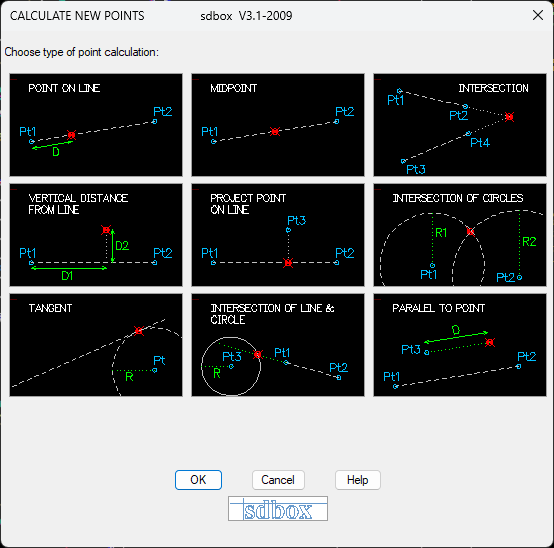
Construction tab for point creation
Practical Applications:
The MLL command is particularly useful for survey drawings, topographic plans, and any application where you need to draw lines to specific coded points or use geometric constructions frequently.
Point Creation Options
The Construction tab provides multiple methods for creating points during drawing operations.
These geometric construction tools allow you to create precise points without leaving the drawing command, significantly improving productivity for complex drawings.
Available Construction Methods
- POINT ON LINE: Specify 2 points defining the line and distance D from the first point.
- MIDPOINT OF LINE: Specify 2 points defining the line. The midpoint is calculated automatically.
- INTERSECTION OF LINES: Specify 2 points for the first line and 2 points for the second line. The intersection point is calculated.
- PERPENDICULAR DISTANCE FROM LINE: Specify 2 points defining the line, perpendicular distance from the first point, and perpendicular length.
- PROJECTION OF POINT ON LINE: Specify 2 points defining the line and the 3rd point to be projected.
- INTERSECTION OF CIRCLES: Specify center and radius of the 1st and 2nd circle.
- TANGENT TO CIRCLE: Specify center and radius of circle and select the tangent on screen.
- INTERSECTION OF LINE - CIRCLE: Specify 2 points of the line and for the circle center point and radius.
- PARALLEL THROUGH POINT: Specify 2 points of the line (for direction) and distance from the 3rd point.
Precision Note:
All construction methods use double precision calculations, ensuring accuracy even in large-scale drawings with complex geometry.
Workflow Tip:
Use these construction tools instead of separate construction lines. They create temporary geometric relationships that don't clutter your drawing with unnecessary objects.
Detailed Construction Tools
Geometric Constructions
POINT ON LINE: Enter the 2 points that define the line and the distance D from the first point.
MIDPOINT OF LINE: Enter the 2 points that define the line. The midpoint is calculated automatically.
INTERSECTION OF LINES: Enter the 2 points that define the first line and 2 points that define the second line. Based on these, the intersection point will be calculated.
PERPENDICULAR DISTANCE FROM LINE: Enter the 2 points that define the line, the perpendicular distance from the first point, and the perpendicular length.
PROJECTION OF POINT ON LINE: Enter the 2 points that define the line and the 3rd point to be projected.
INTERSECTION OF CIRCLES: Enter center and radius of the 1st and 2nd circle.
TANGENT TO CIRCLE: Enter center and radius of circle and select the tangent on the screen.
INTERSECTION OF LINE - CIRCLE: Enter the 2 points of the line and for the circle enter center point and radius.
PARALLEL THROUGH POINT: Enter the 2 points of the line (for direction) and distance from the 3rd point.
Professional Use Cases:
- Surveying and topographic mapping
- Architectural floor plans
- Mechanical part design
- Civil engineering drawings
- Landscape design
Enhanced Block Insertion
During block insertion at scale, you have similar enhanced options as with line drawing.
The SDBox software extends block insertion capabilities, allowing you to:
- Insert blocks by attribute codes
- Use geometric construction points for insertion
- Insert series of blocks at coded points
- Maintain scale and rotation with construction tools
Block Management:
When working with attributed blocks, you can type the attribute code during insertion to automatically place the block at the correct location with predefined attributes.
Scale Considerations:
Blocks inserted with these tools maintain their scale relative to the drawing units, ensuring consistency across different viewports and layouts.
For detailed information about block-specific options and attribute management, see the Block Options documentation.
^ Back to top