Import & Export Block
SDBox Design Software - Import Blocks with continuous numbering and optional coordinate export to file
Import & Export Block ZZB / XYZOUT
Import Block into the Drawing with the ability for simultaneous export to file and multiple naming options during on-screen drawing.
This command allows you to import symbols with continuous numbering and fixed elements, up to complex usage with export of insertion coordinates to a file with predefined elements.
You have the ability to use the command from simple import of symbols with continuous numbering and fixed elements, to complex usage with export of insertion coordinates to a file with predefined elements.
XYZOUT command configuration interface
Command Overview:
The ZZB (or XYZOUT) command provides a comprehensive solution for importing point markers into CAD drawings while optionally exporting their coordinates to external files for use in other applications or devices.
Basic Command Usage
Below is an example that uses most of the command's capabilities. Followed by examples for simpler uses of the command.
[Configuration dialog appears]
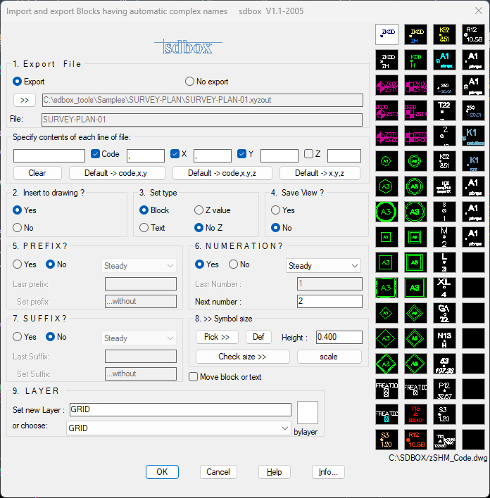
Main configuration dialog for XYZOUT command
Tip:
Always end the command with Enter or right-click, not with Esc, to ensure proper completion of the export file if configured.
Export Options
Export
The points you select on screen are exported to a file of your choice with their coordinates and names.
Without Export
Only Block or Text is inserted into the drawing screen without export to file.
File Selection (>>)
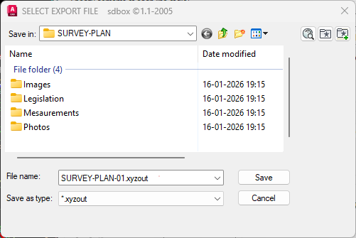
Select your preferred file where the coordinates and names of the points you select on screen will be exported.
The command suggests a file with the drawing name and extension ".xyzout" so you can later distinguish, among many files, which files have been exported by the ZZB command (based on the extension).
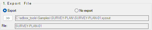
Export option selection dialog
Usage:
Use export when you need to use point coordinates in other software (survey equipment, GIS applications, spreadsheets, etc.).
File Format Configuration
In this section you define the format that each line of the file will have.
If you want to load the file into another program or device, it is often necessary to write specific text at the beginning and end of each line.
The formatting capabilities of each file line are divided (in the order shown above) as follows:
- What will be written at the beginning of each line
- Whether the point name will be written
- What will be the separator between name and X coordinate
- Whether the X coordinate will be written
- What will be the separator between X and Y coordinates
- Whether the Y coordinate will be written
- What will be the separator between Y and Z coordinates
- Whether the elevation Z will be written
- What will be written at the end of the line
File format configuration dialog
Preset Formats
Clear: Clears all file line format options.
Default -> code,x,y: Defines each file line as: Point Name, X, Y
Default -> code,x,y,z: Defines each file line as: Point Name, X, Y, Z
Default -> x,y,z: Defines each file line as: X, Y, Z
Note:
The file content is not deleted, and new command entries will be appended at the bottom. This allows you to accumulate points from multiple drawing sessions into the same file.
Drawing Options
Drawing options configuration
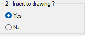
Draw on Screen
Choose whether, in addition to export to file, Blocks or Texts will be drawn on the screen.
If you select no, then you use the command only for point export to file. In this case, you still select points and specify if you want their names. When you select a point, it will be drawn temporarily (and then automatically deleted) so you have an overview of what is being exported to the file.
The case of not drawing points (Block or Text) on the screen is typically used when there are already point codes in the Drawing and you simply want to export their coordinates to a file.
Object type selection
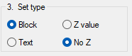
Object Type
Choose the type of object (Block or Text) that will be drawn for each point.
If you select Block, you have the ability to select Block type from the list on the right side of the tab shown below.
Also choose whether for the points drawn on screen, elevation will be given.
View saving option
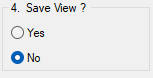
Save View
If you select "Yes", then for each point you select on screen, a View with the same name is saved, which you can later search for with the "View" or "Vports" command of AutoCAD.
^ Back to topBlock Types
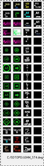
The command provides a library of pre-defined blocks for different point marking needs. Below is an analysis of the block list on the right side of the tab. For ease of writing the help, the Blocks have been numbered.
Key Block numbers




Block library with numbered blocks (1-68)
Key Block Categories
Blocks 1, 2 and 18 use the attribute “ZKOD” for point naming. It is recommended to use these Blocks when inserting points with this command, so that they can be clearly distinguished from other point types (e.g. points inserted with the ITAX command, where the corresponding attribute is named “KOD”).
Block 1 (zSHM_Code.dwg)
Contains only the attribute “ZKOD” for point naming and does not include elevation information.
Block 2 (zSHM_Code-H.dwg)
Contains two attributes: “ZKOD” for point naming and “ZH” for elevation.
Block 18 (zSHM_Code.dwg & zSHM_H.dwg)
In this case, two Blocks are inserted per point:
one Block for the point and its name (attribute “ZKOD”),
and a second Block for the elevation (attribute “ZH”).
For the elevation Block, a new Layer named “****-H” is automatically created.
Blocks 3–5 and 20–22 (zSHM_ST1…6.dwg)
These Blocks contain two attributes: “ZKOD” for point naming and “ZST1…6” for elevation.
They are intended for different elevation display layouts, as the position of the name and elevation varies between Blocks.
Blocks 6–14 and 23–31
(zSHM_KYK1…6.dwg, zSHM_QUA1…6.dwg, zSHM_ROM1…6.dwg)
These Blocks are typically used for simple point insertion with text enclosed in a
circle, square, or diamond.
They contain only naming attributes:
ZSK1…6 (circles),
ZSQ1…6 (squares),
and ZSR1…6 (diamonds).
The naming convention of these Blocks and their attributes is intentionally consistent (same prefix and numeric suffix), allowing batch modifications using commands such as ZZATT, ZCH, ZCS, etc.
Blocks up to number 55
These are commonly used Blocks inserted by the ITAX and ZID commands
and may also be used in combination with the current command.
Blocks 56–68
These positions are reserved for user-defined Blocks.
Custom Blocks may be created in the \\SDBOX directory, following these rules:
- Block names must range from ZSHM_56.dwg to ZSHM_68.dwg.
- The corresponding slide files must be named xyzim56.sld to xyzim68.sld.
Tip:
The names of these Blocks and their attributes are similar (they have the same beginning and all end in a number) so you can make simultaneous changes to all with commands like "ZZATT", "ZCH", "ZCS", etc.
Naming Options
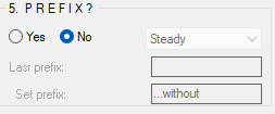
Prefix configuration options
Prefix
A prefix is added to point names and can change predefined during the command execution.
For example, if you want points to have names A1, A2, A3, etc., the prefix is "A".
Fixed: The same prefix is suggested during the command.
Increase by 1: The next alphabetical (or numerical if you selected a number) is suggested each time.
Decrease by 1: The previous alphabetical (or numerical if you selected a number) is suggested each time.
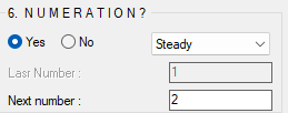
Numbering configuration options
Numbering
Concerns the integer number that participates in the point name.
Fixed: The same number is suggested during the command.
Increase by 1: The next number is suggested each time.
Decrease by 1: The previous number is suggested each time.
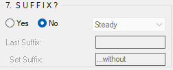
Suffix configuration options
Suffix
A suffix is added to point names and can change predefined during the command execution.
The same rules apply as for the prefix above.
If neither Prefix nor number nor Suffix is selected, then Points are drawn on the drawing screen.
Naming Example
Example for understanding the order PREFIX - NUMBERING - SUFFIX:
If you make the following selections:
- PREFIX: "KA-" and fixed
- NUMBERING: from "1" and increase by 1
- SUFFIX: "ss" and fixed
Then the following names will be suggested during the command:
"KA-1 ss", "KA-2 ss", "KA-3 ss", "KA-4 ss", etc.
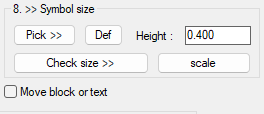
Size configuration options
Size Configuration
Block size or text character height.
The first time you run the command, a height proportional to the ltscale is suggested.
Selection >>: You are transferred to the drawing screen and select Block or Text that have the desired size.
Check size >>: You are transferred to the drawing screen where Text is temporarily drawn with the characteristics you have selected.
Scale: You see the suggested heights according to the print scale.
^ Back to topExecution Example
After completing the configuration, the command continues for drawing on screen.
Select the 1st point on the drawing screen with the mouse. With Enter or right-click the command ends.
Either accept the suggested text with right-click or Enter, or type another. If you don't want a prefix press Space.
Either accept the suggested number with right-click or Enter, or type another. If you don't want a number press "~".
Either accept the suggested text with right-click or Enter, or type another. If you don't want a suffix press Space.
E L E V A T I O N ? [Z= 0.000] [nothing= @ ] < 0.0 >:
Either accept the suggested number with right-click or Enter, or type another, or calculate one by pressing "@".
[Z= 0.000]: The Z of the point as selected on screen is written.
Details for [@ = calculations] see: @ Calculations - Operations
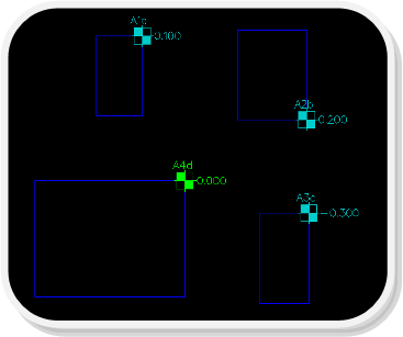
Example of point insertion with configured naming
Continue with new points.
U=Undo: Undoes the last point insertion (and will not be recorded in the file either).
R=Change text position: The insertion point of the Block remains the same and the Attributes change position by quadrant. Use this option when the drawing is dense and you want the point name and elevation to be written in a clear area. This option does not work when Text is inserted.
With Enter or right-click the command ends.
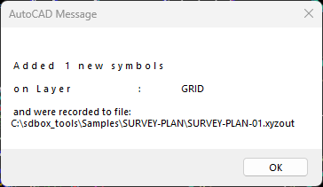
Example of multiple points inserted with automatic numbering
If you press "Yes" the file opens containing what it had before the command and the new points you have inserted with the command.
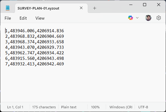
Example of exported coordinate file
Notes:
The Block in position 6 with name "zSHM_KYK1.dwg" is inserted, on the drawing screen, at the same size as "Arithm-Kyklos.dwg" which is inserted with the commands "NNAR" and "NNARR".
Command Usage:
From simple import of symbols with continuous numbering and fixed phrases, to complex usage with export of insertion coordinates to a file with predefined elements.
Tips:
If neither Prefix nor number nor Suffix is selected for point naming, then Points are drawn on the drawing screen.
Always end the command with Enter or right-click and not with Esc.
Simple Example
Follows a simple example for the options you need to make in the command tab to insert texts in a circle as in the image below.
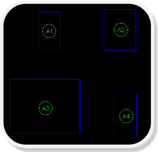
Simple example: texts in circles with automatic numbering
Options in the tab for simple circle text insertion:
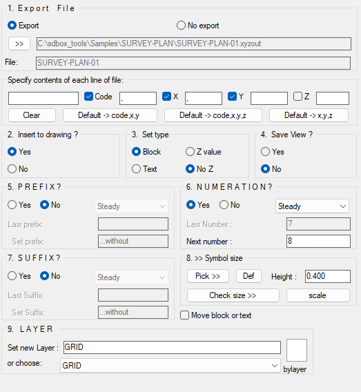
Configuration for simple circle text insertion
Block options for this example:
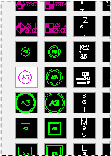
Block selection for circle text insertion
Quick Setup:
For simple numbered points in circles: Select Block type "Text in circle", configure prefix/numbering/suffix as needed, disable export if not required, and set appropriate text height for your drawing scale.