Insert Blocks in a Circle
SDBox Design Software – Insert Blocks with automatic scale and attribute management
Insert Circle Symbol ZKYK
Insert a Block in a circle on the drawing screen, with size proportional to the print scale, and selection from a symbol library.
Select a Block from the symbol library for insertion into the drawing screen. These symbols are inserted into the Drawing at a size proportional to the print scale so they print clearly.
You can enrich the library with your own symbols and use them easily in any Drawing, as you can also add a description for each Block to remind you of its use.
Enter the LAYER for ''Block in circle'':
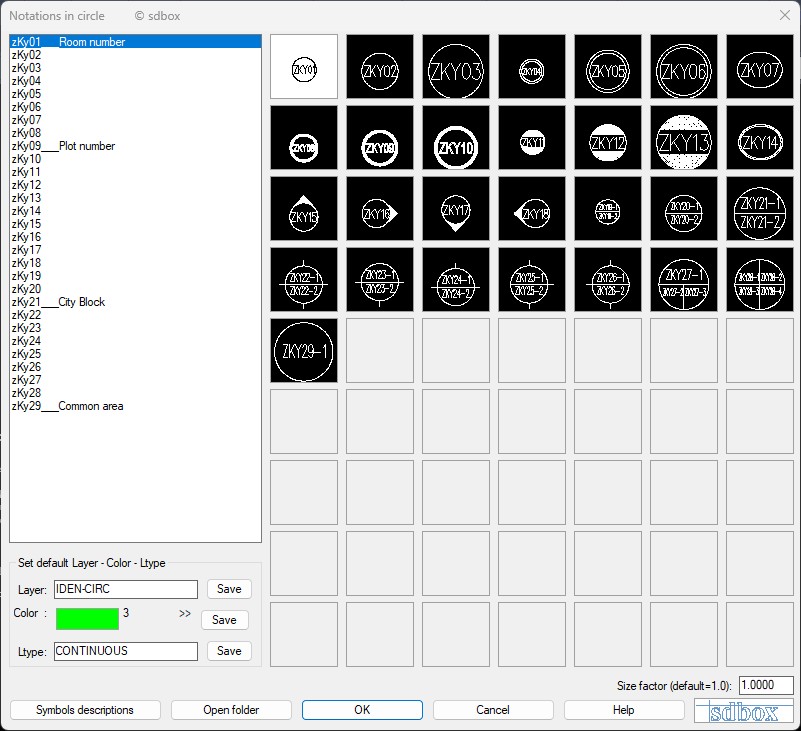
ZKYK command dialog with symbol list and preview
Layer selection
See the General Command 'Layer Selection'.
Symbol selection
Opens a dialog where the Blocks (with their descriptions) located at \\SDBOX\SBL\zKykloi are displayed.
You can modify existing or create new Blocks in this location.
When creating a new Block, you must name it from zKy01.dwg to zKy63.dwg (in continuous numerical sequence) and also create the corresponding slide with the same name for it to appear in the images on the right side of the dialog.
From the list on the right or the images on the left, you can select the symbol to insert into the Drawing. Double-click automatically switches to the drawing screen for insertion of the selected symbol.
If a drawing-symbol does not have a slide, “No Slide” appears in its place.
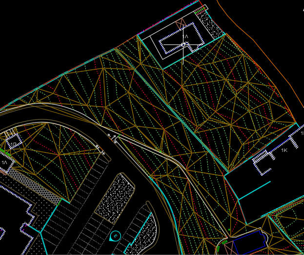
Block editor
<..if you pick a point ENTER=angle 0.0000>
On the drawing screen you pick:
- A point to insert the first Block, and
- A second point for the angle, or type an angle value.
If you do not want to specify an angle, after the insertion point press Enter, right-click, or Space, and the symbol is inserted horizontally.
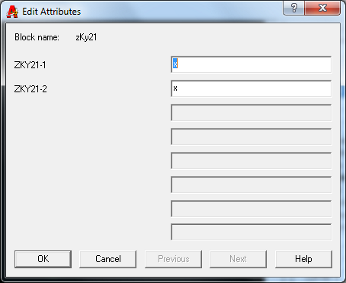
Block editor
You enter values for the attributes of the Block you are inserting. The first time a Block is inserted, the value “x” is suggested for each field.
The values you enter are saved and suggested again when you insert the next Block.
Next “O.T. Symbol (zKy21)” ? R/S/U/Y/N <Yes> :
Options after insertion
R = Reverse direction: Changes the Block’s orientation (AutoCAD mirror command) without changing text reading direction. Useful for linearly-arranged Blocks to fit in a clean area of the drawing. For symmetrical Blocks (circles, squares) this option shows little visual difference.
S = Change Symbol: Re-opens the command dialog where you can choose a different symbol type for insertion.
Y = Yes / Continue: The command continues with insertion of the next symbol.
N = No / End: The command ends and reports how many symbols were inserted into the Drawing.
Notes:
Do not rename existing drawings. (The command will not work correctly.)
When creating a new Drawing-symbol, also define the insertion point with the AutoCAD base command.
The folder \\SDBOX\SBL_zO can contain a maximum of 63 drawings (in continuous numerical sequence). More drawings will not participate in the command.
For each drawing, create the corresponding slide with the same name using the AutoCAD mslide command.
Besides the ZKYK command, you can open the description file with the ZKYK1 command.
Besides the ZKYK command, you can open a file listing the Blocks that participate in the command with the ZKYKLIST command.
Besides the ZKYK command, you can open the symbols folder with the ZKYKDIR command.
Command Usage:
The command’s ability to save the values you enter for the Block’s fields and suggest them for the next Block is useful when you want to insert a Block into the Drawing with the same field values and still be able to make changes each time.
The symbol descriptions displayed in the command dialog help you distinguish visually similar Blocks from each other.
Tips:
The choices you make each time you run the command are saved and suggested thereafter when you run the command again in the same Drawing or in any other Drawing.
If you agree with what is suggested (as the last choice) when the dialog opens, you can press Enter or Space to accept them and continue with symbol insertion on the drawing screen.
Symbol Descriptions ZKYK1
Opens the file that contains the descriptions of the symbols inserted into the Drawing with the ZKYK command.
Opens the file \\SDBOX\ZKYK.dat where you can view, correct, or add new descriptions that appear in the dialog opened by the ZKYK command.
In this example we have descriptions for 2 symbols: zKy01.dwg and zKy21.dwg.
The procedure is as follows:
Write a new line in the opened file:
"zKy01 ? Room Number"
That is: Symbol name “?” Description.
This will appear in the ZKYK command dialog as: “zKy01__Room Number”.
The list in the dialog will be updated after you run the command again.
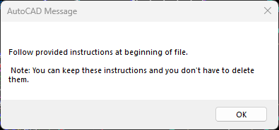
Editing the symbol description file
A message appears reminding you that the file contains instructions at the top that you should not delete.
Descriptions are given to remind you of each symbol’s use. They are not used for anything else.
Notes:
You can copy the symbol list with the ZKYKLIST command into the description file, delete the “.dwg” extensions, and complete the descriptions.
You can open the symbols folder with the ZKYKDIR command.
Command Usage:
The symbol descriptions that appear in the ZKYK command dialog help you distinguish visually similar Blocks from each other.
The ZKYK1 command can also be executed from the ZKYK dialog by pressing the “Symbol Descriptions” button.
Tips:
It is recommended to give descriptions for all Blocks that participate in the ZKYK command so you have a complete overview and can easily insert the Block you want each time.
Circle Symbols List ZKYKLIST
Opens a file containing all the drawing-symbols inserted into the Drawing with the ZKYK command.
Opens the file \\SDBOX\SBL_zO_LIST.dat which lists by name all the Drawings contained in the folder \\SDBOX\SBL_zO.
You can copy any names you want and paste them into the file \\SDBOX\ZKYK.dat (of the ZKYK1 command) and complete the descriptions.
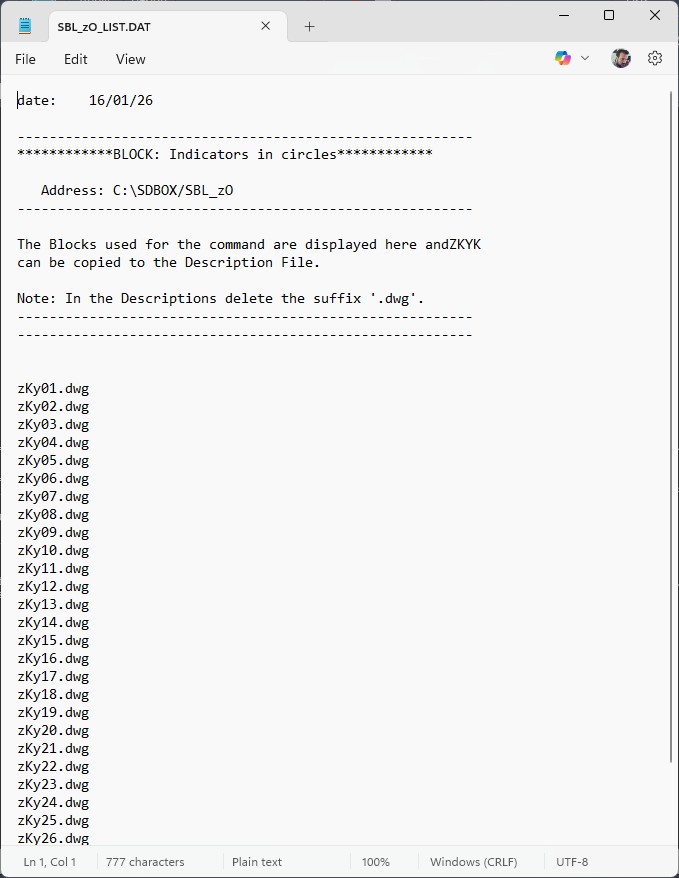
List of all symbols in the ZKYK library
Notes:
Every time you run the command in any drawing, it always opens the same file at \\SDBOX\SBL_zO_LIST.dat.
You can save it with a different name or in a different location for your own use.
Command Usage:
The opened file, which lists by name all the Drawings contained in the folder \\SDBOX\SBL_zO that participate in the ZKYK command, is not used as a file in any command.
It opens so you can have an overview of the existing Blocks, or to copy the Block names (usually to paste them into the symbol description file and complete the descriptions).
Tips:
You can first run the ZKYKLIST command, leave the file open, then run the ZKYK1 command, so with both files open you can perform the above copy-paste operations.
You can open the symbols folder with the ZKYKDIR command.
Open Folder ZKYKDIR
Opens the folder containing the drawing-symbols inserted into the Drawing with the ZKYK command.
Opens (via Windows) the folder \\SDBOX\SBL_zO that contains the drawing-symbols (*.dwg) and the corresponding slides that appear in the ZKYK command dialog.
You can create new Drawings (and corresponding Slides) in this folder.
The names of the Drawing-symbols and their corresponding slides can be from zKy01 to zKy63 (in continuous numerical sequence) and nothing else.
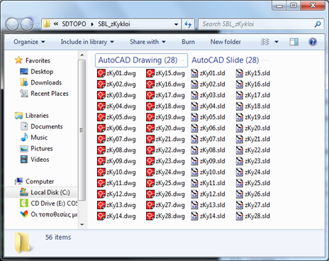
Contents of the ZKYK symbols folder
Notes:
You cannot move the folder to another location because the ZKYK command only reads the address \\SDBOX\SBL_zO.
Command Usage:
Do not rename existing drawings. (The command will not work correctly.)
When creating a new Drawing, also create the corresponding Slide with the AutoCAD mslide command.
Tips:
When creating a new Drawing-symbol, also define the insertion point with the AutoCAD base command.
The folder \\SDBOX\SBL_zO can contain a maximum of 63 Drawings (in continuous numerical sequence). More drawings will not participate in the command.