Files - Tasks - Google Earth
SDBox Design Software - Command guide for file management, task control, paper insertion, tables, details, and folder access in CAD drawings
Tasks Check CEC
Opens a tab where you can mark which tasks, from a predefined task list, have been completed.
You can view and check off completed tasks from a predefined checklist. The displayed list can be specified or changed using the ZVFE command or the CEC1 - CEC5 commands.
Task List Selection
The tasks displayed in the tab are selected from one of the 5 lists of the ZVFE command or the CEC1 - CEC5 commands.
ZOOM in Drawing >>:
The tab is temporarily hidden, and you are moved to the drawing screen where you can navigate through the drawing to check it.
Press Enter or right-click to return to the tab.
Navigation is done with the mouse on the screen (middle scroll wheel for zoom in, zoom out, and pan).
During navigation, you can execute several drawing viewing and configuration commands from the Toolbar that opens.
Note: If you execute other AutoCAD commands (outside the Toolbar), the command will be terminated.
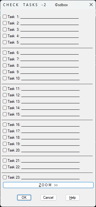
Tasks check interface
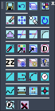
Navigation toolbar during drawing review
Notes:
The command provides a systematic way to track project completion stages directly within your CAD environment.
Command Usage:
Use this command during project reviews, quality checks, or when collaborating with team members to ensure all drawing tasks are completed.
Selection - Configuration ZVFE
Opens a tab where you can view and edit the files that participate in various commands.
You can also select which file category each command will read when executed, including the CEC command.
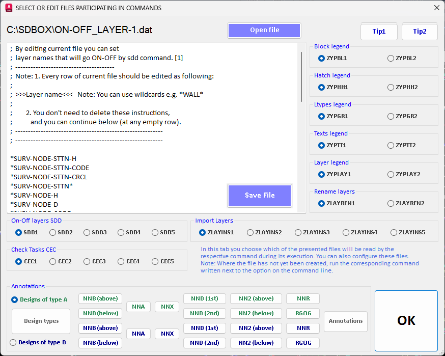
Command files configuration interface
Tips:
This command serves as a central configuration panel for multiple SDBox commands, allowing you to customize which data files each command uses.
Editing - 1, 2, 3, 4, 5 CEC1-5
Select which of the 5 available files the CEC command will read during execution to display the corresponding tasks in the tab.
By typing CEC1, CEC2, CEC3, CEC4, or CEC5 you define which file the command will read (1, 2, 3, 4, or 5 respectively), and you can also edit it if desired.
You can do the same by running the above ZVFE command.
File creation / editing
CEC1: Creates and updates file //SDBOX/ERGASIES1.dat
CEC2: Creates and updates file //SDBOX/ERGASIES2.dat
Each time you run one of the above commands, the corresponding .dat file is set as default and the CEC command searches for task lists in it.
If you don't run any of the 5, then ERGASIES1.dat is set as default.

File selection prompt
Esc or No: The command ends and file //SDBOX/ERGASIES2.dat is set as the one that the CEC command will read.
Yes: Again the above file is set as default and the command continues by opening it for editing.
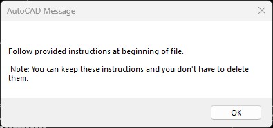
First execution message
Editing the task list
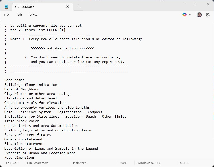
Editing the task list file
If you subsequently run the CEC command, the tasks as you have defined them in the above file will appear in the tab.
Notes:
When the explanation files are fully defined, you use the CEC1-CEC5 commands only to determine which file the CEC command will read.
Command Usage:
Whenever you want to configure the task list file or define which file the CEC command will read for task lists.
Tips:
Create separate task lists for different project types (e.g., architectural, mechanical, electrical) and switch between them using these commands.
Paper A4 - A0 XARTI
Insert a Paper Block from A4 to A0 size according to the print scale.
Inserts a paper border/title block of standard sizes (A4, A3, A2, A1, A0) scaled appropriately for your drawing's print scale.
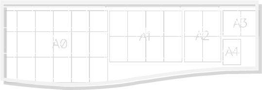
Paper size and scale selection
Selection options
You select the scale and paper type (A4, A3, A2, A1, A0).
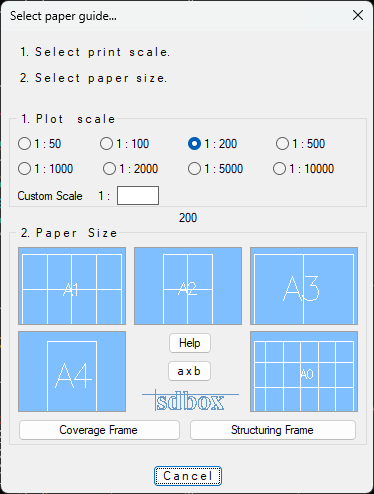
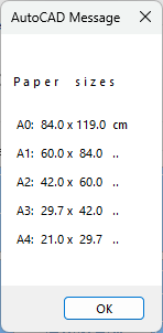
Scale and paper type selection interfaces
Insertion parameters
Then on screen you provide Layer, insertion point, and rotation.
Note: The Layer suggested as default by the command is defined not to print.
Notes:
The paper block includes a standard title block area for project information, scale indication, and revision history.
Command Usage:
Use this command when preparing drawings for printing or when creating drawing sheets with standardized borders.
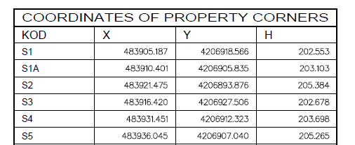
Table from File ZPFL
Select a file and column separator, and a table is drawn listing the file contents.
This command imports tabular data from external text files and creates a formatted table in your drawing.
File and table configuration interface
File selection and configuration
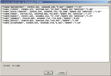
File selection dialog
You can select different column separators:
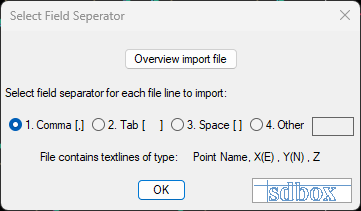
Column separator options
Text format and other options:


Text formatting and additional options
Details: Layer Selection
Table preview
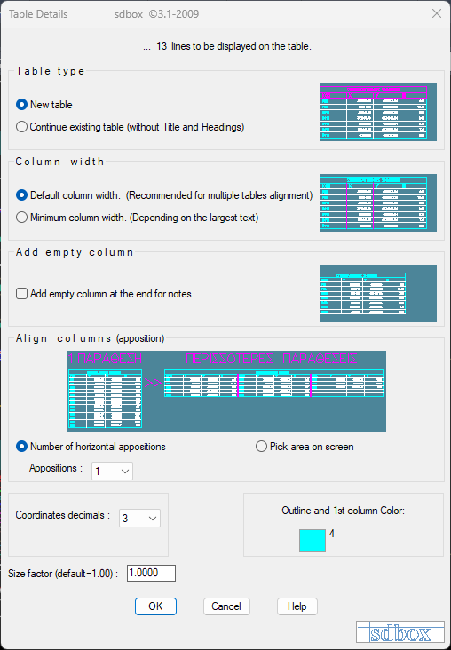
Table preview before insertion
You select the table insertion point and then provide the Title.
The height of the texts in the Table that is finally drawn on screen is set automatically according to the print scale.
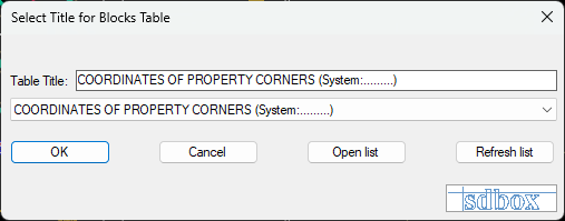
Table insertion point selection
Notes:
This command is ideal for importing schedule data, material lists, or any tabular information from external sources into your CAD drawing.
Command Usage:
Import Excel data (saved as CSV or tab-delimited text) or any other tabular data into your drawing as a formatted table.
Drawing Detail Cutout ZLPT
Select an area of the drawing which is redrawn in another area, scaled according to the detail print scale and the main drawing print scale.
Creates a detail view of a specific area of your drawing at a different scale for clarity.
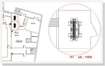
Detail creation interface
Process steps:
- Enter the Detail Number. This number is drawn both in the original area of the Drawing and in the area where the Detail is drawn.
- Select the center point of the detail area.
- Provide the circle radius by number or dimension on screen.
- Select the point (outside the rest of the Drawing) where the Detail will be drawn.
- Ask if you want to Trim objects outside the circle.
- Enter the print scale of the Detail.
- Confirm the print scale of the rest of the Drawing. Based on the 2 scales, the enlargement or reduction is calculated and applied to the Detail objects.
- Place the Detail Title at the desired position.
Notes:
The detail maintains all object properties and layers, ensuring consistency with the main drawing.
Command Usage:
Create enlarged views of complex areas, connection details, or any part of your drawing that requires closer examination at a larger scale.
Tips:
Use different detail numbers for organization and reference in your drawing documentation.
Open Drawing Folder ZDRC
Opens (via Windows) the folder where the current drawing is located.
The command is designed for easy access to the drawing's folder at any time, without needing that folder to be constantly open.
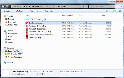
Opening the drawing folder
Command Usage:
Quickly access supporting files, xrefs, images, or other documents stored in the same folder as your drawing.
Tips:
This is especially useful when working with drawings that have multiple referenced files in the same directory.
File Preview ZSFILE
Opens a tab where a selected file is displayed and you have the ability to apply filters and extract portions of the file.
Select the file from a Windows dialog, and then a tab opens where you can view the file, apply filters in relation to the phases or numbers it contains.
If you apply a filter, you can export the result to a new file. You can always view the file in its original form.
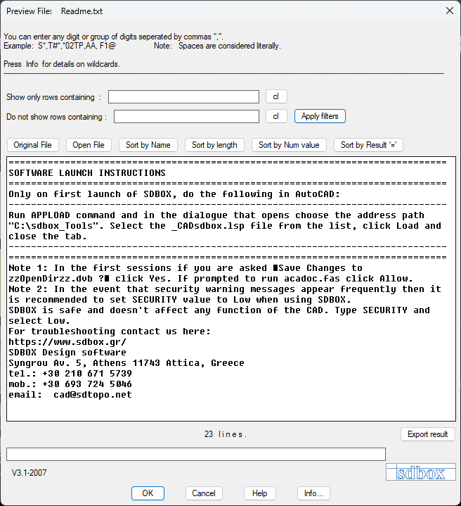
File preview and filtering interface
Notes:
- Uppercase and lowercase letters are considered different.
- If you want to apply a filter for more than one phrase, write them all in the corresponding field with commas in between.
- Spaces are taken into account. (Don't put spaces before or after the comma that separates the different phrases you're searching for)
- You have 2 fields for applying filters. In the first write what you want the phrases to contain and in the other what you don't want them to contain. A combination of these two fields can be made.
- After applying filters you can export the result to a new file.
- You can open the displayed file at any time.
For example, if you want to isolate lines that start from 100 to 299, then write [12]##* in the filter field to show lines that contain, and you get the following result:
Command Usage:
Preview and filter large data files, coordinate lists, or any text-based data before importing into your drawing.
Open SDTOPO Folder ZSSDD
Opens the SDBOX program folder.
The command is designed for easy access to SDBOX files or folders at any time.
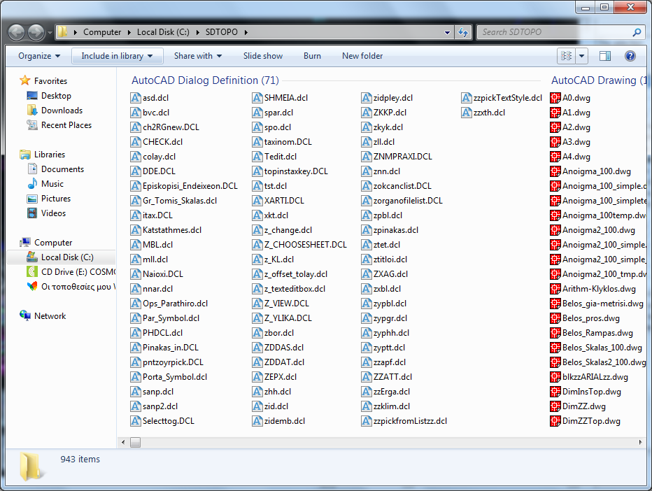
SDBOX program folder
Command Usage:
Access configuration files, support files, or other resources stored in the SDBOX installation directory.
Tips:
Use this command to quickly access and modify SDBOX configuration files or check for available resources.