Study Composition
SDBox Design Software - Guide for Composing Topographic and Architectural Surveys
This manual provides comprehensive instructions for composing Topographic diagrams and Architectural Surveys (Plan, Section, Elevation) using SDBOX software. It includes step-by-step guides, examples, and settings for optimal results.
SURVEYS:
All tools are provided for the complete composition of Topographic and Building survey drawings. The process is presented in detail in the guides below.
Starting from version 3.00, new tools for constructing triangles (DTM) and contours have been added.
Note: The plot styles (*.ctb files) that accompany the application are configured so that the final printed drawings meet high standards of clarity and detail.
Instructions for Topographic Composition
Complete guide for creating Topographic diagrams with SDBOX.
Detailed Topographic Composition Instructions
Step-by-step guide for diagram composition with SDBOX
Example Images:
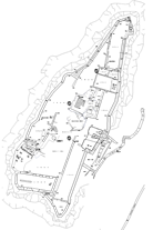
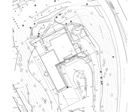
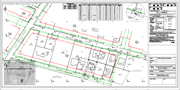
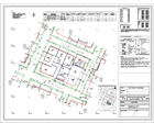
Topographic Diagram Examples - Click on images for details
^ Back to TopInstructions for Architectural Plan Composition
Guide for composing architectural plans with all necessary elements and symbols.
Detailed Plan Composition Instructions
Step-by-step guide for plan composition with SDBOX
Explanation of Layers and example of a plan drawing
Plan Samples:
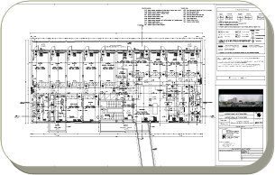
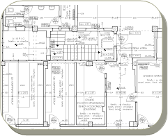
Architectural Plan Examples - Click on images for details
^ Back to TopInstructions for Architectural Section Composition
Guide for composing architectural sections with detailed analytical elements.
Detailed Section Composition Instructions
Step-by-step guide for section composition with SDBOX
Explanation of Layers and example of a section drawing
Section Samples:
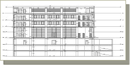
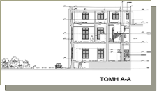
Architectural Section Examples - Click on images for details
^ Back to TopInstructions for Architectural Elevation Composition
Guide for composing architectural elevations with attention to detail and materials.
Detailed Elevation Composition Instructions
Step-by-step guide for elevation composition with SDBOX
Explanation of Layers and example of an elevation drawing
Elevation Samples:
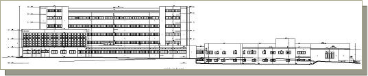
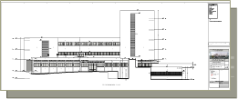
Architectural Elevation Examples - Click on images for details
^ Back to TopSetting Default or Minimum Sizes 50100SCALE
Setting indication and station sizes for scales 1:100, 1:50, and smaller.
Default:
The indication and station sizes are inserted into the drawing "larger" to allow for printing at larger scales as well.
Minimum:
The indication and station sizes are inserted into the drawing with the minimum size so that they remain clear when printed at the design scale set in the drawing.
Explanation:
The sizes of indications and stations for scales 1:100, 1:50, and smaller are inserted into the drawing with almost double the size (compared to those of other scales).
This happens in the program's default settings to allow a drawing composed, for example, for scale 1:50 to be printed also at 1:100 while keeping texts and symbols as legible as possible.
It is common for plans at 1:50 or 1:100 to be printed on small paper (for construction sites or presentations), and for this reason, in the program, objects are inserted "larger" so they can be read at larger scales as well.
With the 50100Scale command, you have the ability to change this setting and define the sizes of symbols and texts to be the minimum, ensuring clarity and space efficiency in the drawing.
At any time, you can restore the program's default settings as described above.
Note:
The other scales (1:200, 1:500, etc.) are not affected by this command.
Default vs. Minimum Comparison:
In the image below, the differences between the two options (default and minimum) are shown in blue. Objects in black remain the same in both options.
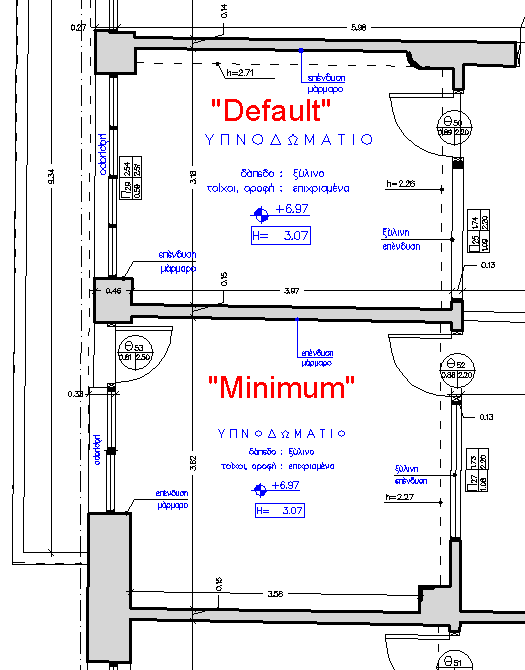
Differences between Default (default) and Minimum (minimum) sizes
^ Back to Top