TIN / DTM Tools
SDBOX command reference for terrain triangulation, breaklines, surface inspection and triangle editing inside AutoCAD, BricsCAD, progeCAD, GstarCAD and ZWCAD
 TIN / DTM video playlist
 Video: TIN / DTM overview
 Video: DTM and triangle editing
📈 Contours — Complete Guide
Video: DTM and triangle editing
📈 Contours — Complete Guide
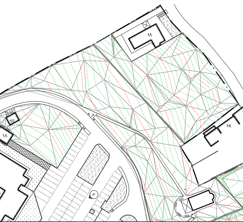 2D Triangulation (TIN)
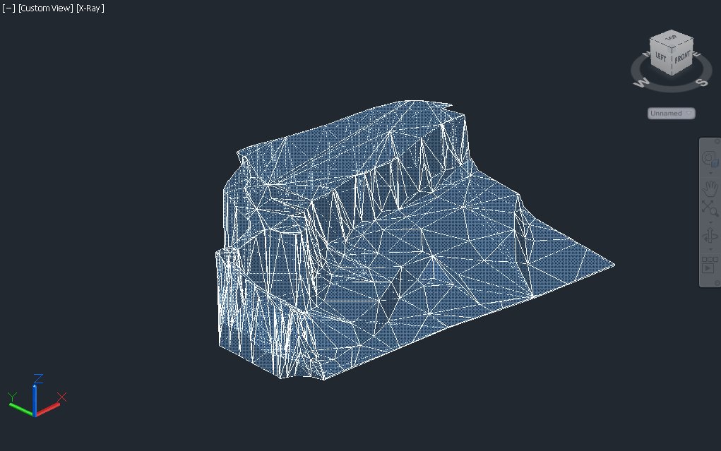
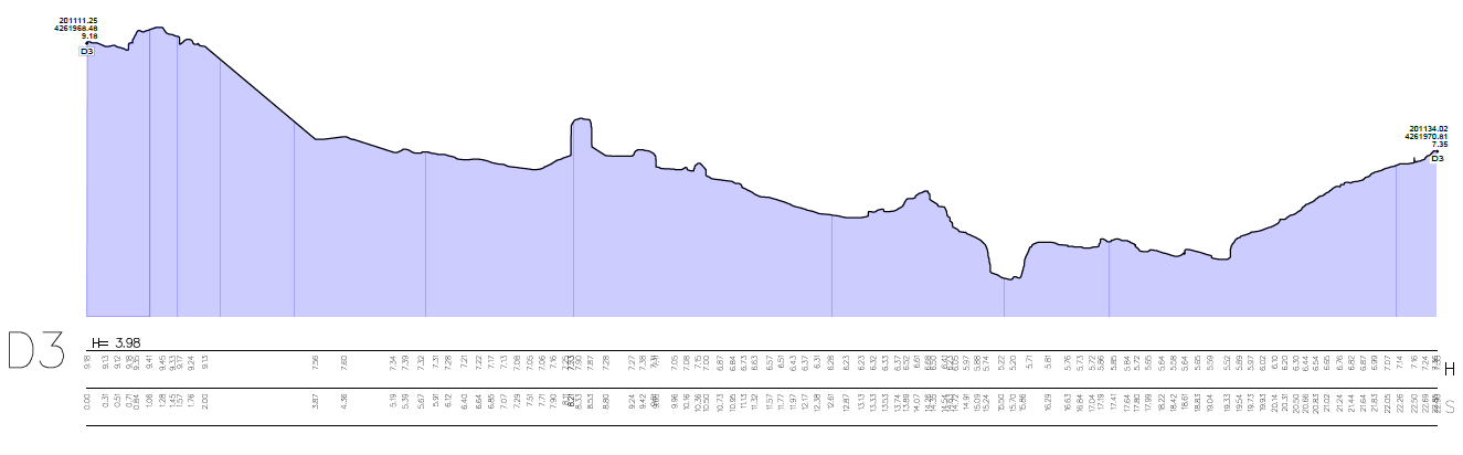 3D TIN Surface
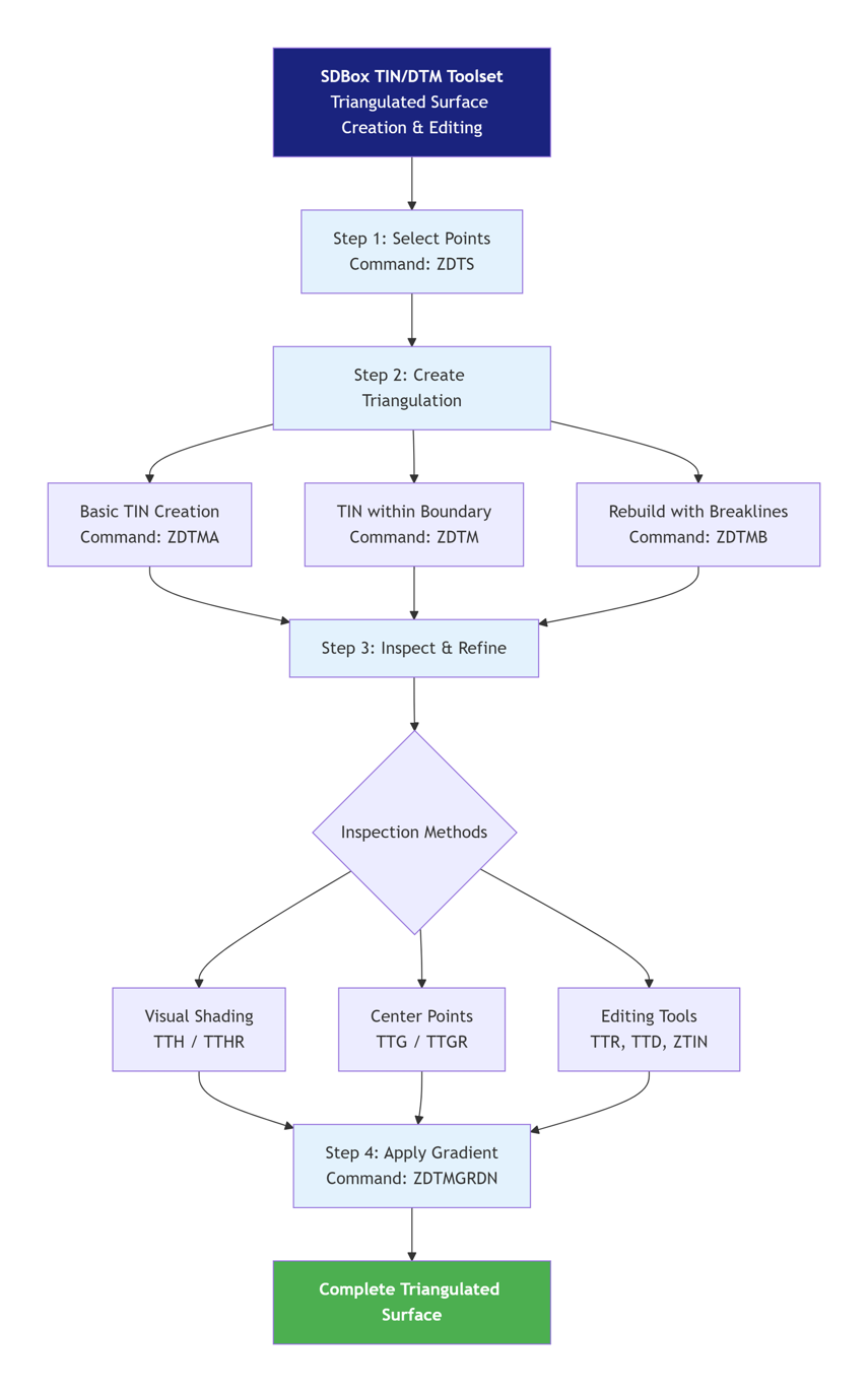
 Terrain & Volume Workflow
Overview
The SDBOX TIN / DTM toolset lets you create, inspect and edit triangulated terrain surfaces directly inside the CAD drawing.
A typical terrain-model workflow is:
- Define the points that will participate in the terrain model with ZDTS.
- Create the triangulation with ZDTMA, or limit it to a closed boundary with ZDTM. Where required, rebuild the model using breaklines with ZDTMB.
- Inspect and refine the triangulation using shading (TTH / TTHR), triangle-center checks (TTG / TTGR) and local editing tools (TTR, TTD, ZTIN).
- Export triangle geometry when needed with ZXTIN.
Compatibility
These commands are available on the supported SDBOX CAD platforms — AutoCAD, BricsCAD, progeCAD, GstarCAD and ZWCAD — according to the installed SDBOX edition.
Add New Points TTS
Adds supplementary survey points for use in the terrain model while keeping the existing point numbering structure.
Use this command when additional terrain points are required after the original survey-point set has already been established.
Typical workflow
- Run TTS and define the first number for the new points.
- Pick the locations of the supplementary points and calculate or assign their elevations as required.
- Continue with ZDTS and the relevant triangulation tools to include the new points in the terrain model.

Elevation calculation options
^ Back to top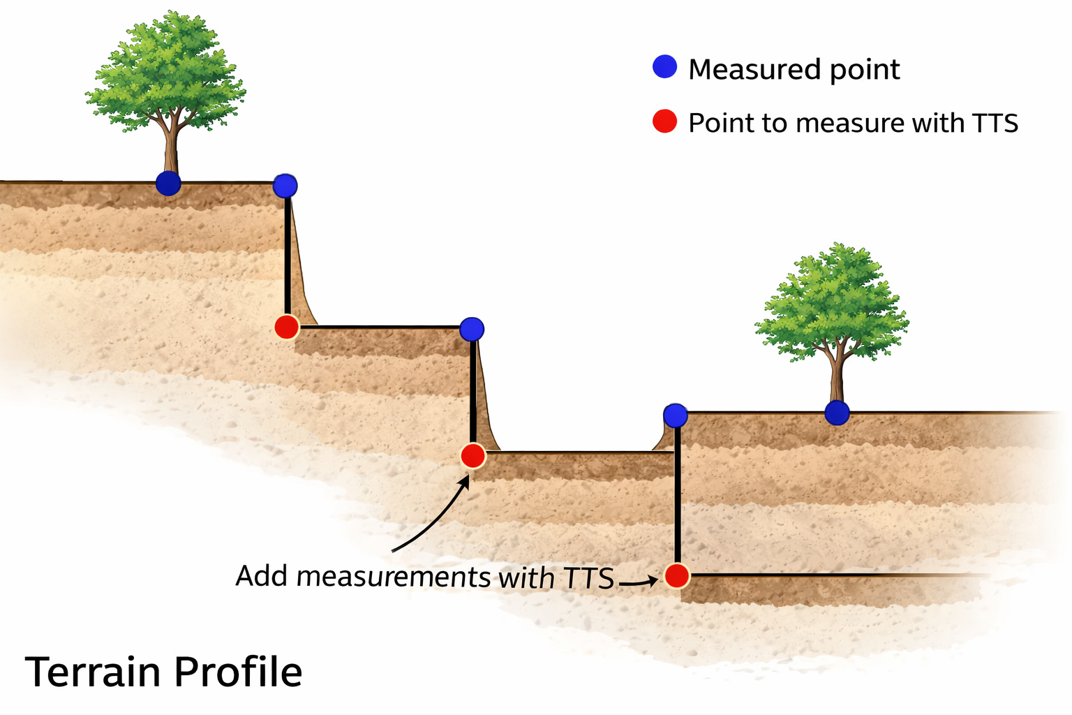
Example: measured points and additional terrain points
Select Points for DTM ZDTS
Defines the survey points that will participate in the TIN / DTM triangulation.
This command defines the active terrain-point set used by the SDBOX triangulation commands.
Selection
Select the required points in the drawing. For advanced selection by object type, block or attribute, see Object selection with filters.
Notes
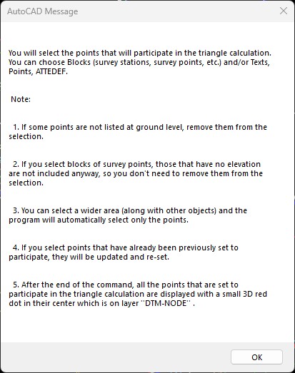
Selecting DTM points in the drawing
Selection options / filters
^ Back to topDraw Standard Triangles ZDT1
Sets the current triangulation mode to create normal terrain triangles.
New triangles are then treated as normal terrain triangles rather than exclusion triangles.
Tip
Use ZDT2 instead when the triangles should define areas excluded from terrain processing.
Draw Exclusion Triangles ZDT2
Sets the triangulation mode to create exclusion triangles.
Use exclusion triangles for areas that should not participate in subsequent terrain processing, such as buildings, voids or other non-terrain areas.
Typical workflow
- Switch to ZDT2.
- Create or select the triangles that define the excluded area.
- Continue with the required terrain-model operations after the exclusion area has been defined.
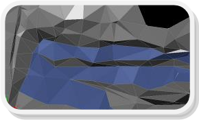
Exclusion triangle definition
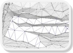
Result after applying exclusion triangles
^ Back to topOpen-Boundary Triangulation ZDTMA
Creates a triangulation without forcing a closed outer boundary.
Use this command when the terrain model should be generated directly from the selected point set without being clipped to a predefined closed boundary.
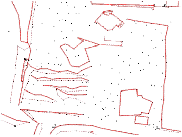
Open-boundary triangulation example

Example without a maximum triangle-side limit

Example with an appropriate maximum triangle-side limit
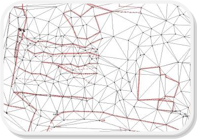
Resulting open-boundary triangulation
^ Back to topCreate / Edit Individual Triangles ZTIN
Creates individual triangles manually for local terrain-model editing.
Use it for local corrections where the automatic triangulation does not represent the required terrain connection.
Rebuild Using Breaklines ZDTMB
Rebuilds the triangulation while respecting defined breaklines.
Breaklines represent terrain discontinuities or controlled linear features, such as curbs, ridges, channels or pavement edges, that the triangulation must follow.
Recommended steps
- Define the participating points with ZDTS.
- Draw or select the required breaklines according to the DTM layer setup.
- Run ZDTMB to rebuild the terrain triangulation using those breaklines.
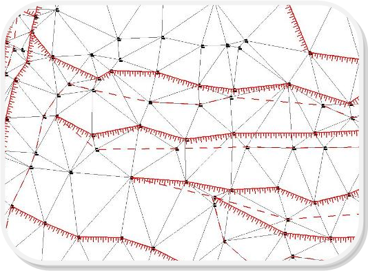
Triangulation rebuilt using breaklines
Selection options / filters
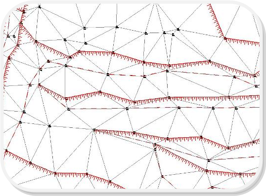
Result after rebuild
^ Back to topTriangulation Inside a Closed Boundary ZDTM
Creates the terrain triangulation inside a selected closed polyline.
Use this command when the terrain model must be limited to a defined project or survey boundary.
Workflow
- Draw or select the closed polyline that defines the terrain-model boundary.
- Ensure the participating points are defined with ZDTS.
- Run ZDTM and select the closed boundary.
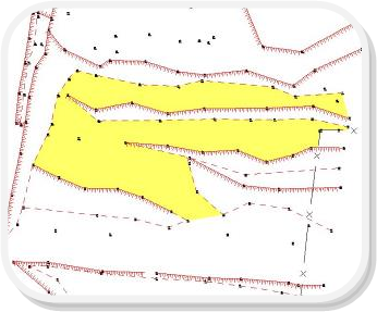
Boundary selection for closed-area triangulation
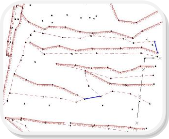
Command options (example)
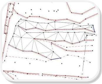
Triangulation result inside boundary
^ Back to topFind Missing Triangles TTNO
Identifies missing triangle connections in the current triangulation.
Use this during terrain-model checking to locate gaps that may require a manual triangle or a triangulation rebuild.
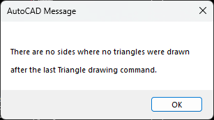
Example of a detected missing triangle connection
^ Back to topShow Triangle Centers TTG
Creates center markers for the currently drawn terrain triangles.
The center markers provide a quick visual check of the current triangle set and help identify missing or outdated terrain triangles.
Refresh Triangle Centers TTGR
Updates the triangle-center markers after triangulation edits.
Run this after deleting, swapping, adding or rebuilding triangles so the center markers match the current triangulation.
Note
A missing center marker can indicate that the corresponding triangle is missing or that the center markers need to be refreshed.
Shade Triangles TTH
Applies temporary shading to the terrain triangles for visual inspection.
Shading can make incorrect connections, spikes and local surface inconsistencies easier to identify.
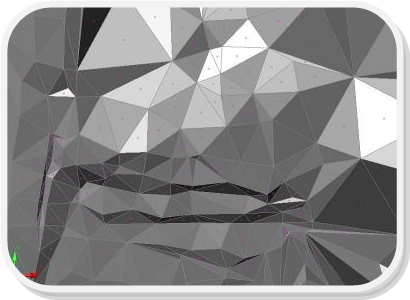
Shaded triangles for visual inspection
Tip
Use TTHR to remove the shading and return to the normal triangle display.
Remove Triangle Shading TTHR
Removes the temporary shading applied to the terrain triangles.
Use it after visual inspection to return to the normal triangulation display.
Send Triangles to Back TTB
Sends the terrain triangles behind the other drawing objects.
Useful when the triangle edges interfere visually with survey or design geometry.
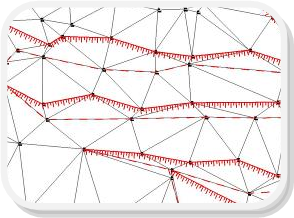
Triangles displayed behind other entities
^ Back to topBring Triangles to Front TTF
Brings the terrain triangles in front of the other drawing objects.
Use this when the triangle edges need to remain clearly visible during inspection or editing.
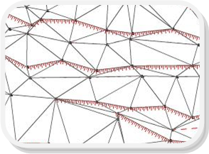
Triangles displayed in front of other entities
^ Back to topSwap Triangle Diagonal TTR
Changes the common diagonal of two adjacent triangles for a local triangulation correction.
Use it when two adjacent triangles are connected in the wrong direction and a local correction is preferable to rebuilding the complete terrain model.
Note
Use the command Undo option if a triangle pair is changed unintentionally.
Delete Triangle TTD
Deletes an individual terrain triangle.
Use it for local cleanup when an unwanted triangle should be removed before further editing or retriangulation.
Toggle Triangle Layers TTV
Toggles the visibility of the DTM triangle layers.
If the triangle layers are visible they are turned off; if hidden, they are turned back on.
Tip
Useful for switching quickly between the terrain model and the rest of the drawing during inspection and editing.
Toggle Point Layers SSV
Toggles the visibility of the point layers used by the DTM workflow.
Use it together with TTV to switch quickly between points-only, triangles-only and combined views.
Bulk Delete Triangles ZEEDTM
Deletes multiple terrain triangles in one operation.
Use this when part or all of an existing triangulation needs to be removed before rebuilding or editing.
Selection options / filters
Note
After deleting the required triangles, rebuild or edit the terrain model with the appropriate triangulation commands.
Delete Triangles Inside Polylines ZDTMD
Deletes terrain triangles located inside selected closed polylines.
Use this command to remove terrain triangles from closed areas that should not be part of the modeled surface, such as building footprints or other excluded zones.
Workflow
- Select one or more closed polylines that define the areas to exclude.
- SDBOX removes the terrain triangles inside those boundaries.
- Where useful, isolate the relevant DTM layers before running the command to simplify selection.
Export Triangles to File ZXTIN
Exports selected terrain triangles to a coordinate-based text file.
The exported triangle geometry can be used for data exchange with other applications or workflows that accept triangle-vertex coordinates.
Exported data
Each triangle is written as three vertices (A, B and C) with their X, Y and Z coordinates:
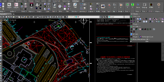
Triangle export example
Tip
Use selection filters when only part of the terrain model should be exported. See Object selection with filters.
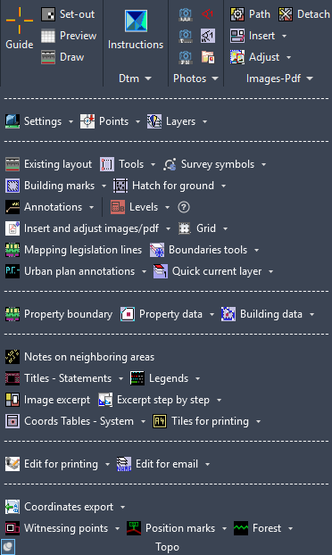
DTM Ribbon
^ Back to top