Block Attribute Table
SDBox Design Software - Command guide for creating tables displaying Block attribute contents and coordinates in CAD drawings
Block Table - Main Command ZPBL
A table is drawn on screen with columns displaying the contents of selected Block Attributes and their coordinates.
This command creates a formatted table in your drawing. The table columns display the values of specific Attributes and the coordinates (X, Y, Z) of the Blocks you select. The table text height is automatically set according to the print scale for clear output.
Command Overview
The process is the same across the various command variants (ZPBL, ZPB1-4, ZPPOL, ZPTR, ZPRP, ZPID, ZPIK). The only differences are in the suggested Blocks to select, the Attributes to record, and the table title, which are saved and suggested in each new use per variant.
The key difference between ZPBL and ZPB1 - ZPB4 is that ZPBL allows free selection of Blocks and Attributes each time, while ZPB1 - ZPB4 save your selections and suggest them in every new drawing. This lets you use them as categories of default settings for frequent or specific use cases.
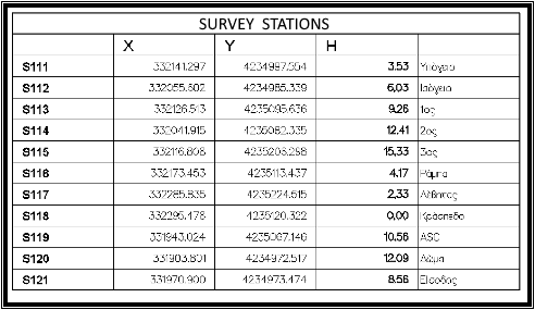
Final table example
Steps
- Run the command ZPBL.
- Define Block names and Attributes: Specify which Block names will participate and which Attributes (and in what order) will be recorded in the table.
- Select Blocks in the drawing: Choose the Blocks you want in the drawing area using selection filters.
- Configure Table Properties: A dialog opens where you set the table's properties (sorting, columns, etc.).
- Pick Insertion Point: Select a point on screen or two points if you selected "Select area in drawing."
- Choose Sorting: Select how the table rows should be sorted.
- Enter Title: Finally, choose a title and the table is automatically drawn.
Detailed Process
1. Define Block Names and Attributes
You define the names of the Blocks that will participate and the Attributes (and their order) that will be recorded in the table.
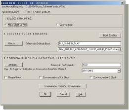
Block selection interface. Details
2. Select Blocks in the Drawing
Select the desired Blocks in the drawing area based on filters.
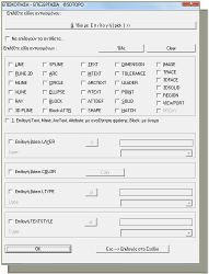
Selection with filters. Details
3. Configure Table Properties
After selecting the Blocks, the following dialog appears where you configure the table properties:
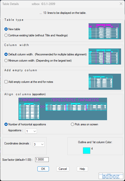
Table properties configuration dialog
4. Pick Insertion Point and Area
Then select a point on the screen or two points if you have selected "Select area in drawing."
5. Choose Sorting Method
- Alphanumeric Sorting: Table rows are sorted alphanumerically (a, b, c,... 1, 2, 3, 4,…,10, 11..).
- In the order they were selected: The rows show the object data in the order you selected them on screen.
- In the order they were drawn: Chronological order of drawing (oldest appears first).

Choose Sorting Method
\6. Final Table Creation
Finally, you choose a title and the table is automatically drawn. The text height of the final table drawn on screen is set automatically according to the print scale.
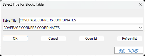
Title of table
Notes:
The table is created as an AutoCAD Block itself, allowing for easy movement, scaling, or modification as a single entity.
Ensure the Blocks you select contain the Attributes you specified; otherwise, those cells will appear empty in the table.
Command Usage:
Use this command to generate coordinate lists, door/window schedules, equipment lists, or any other tabular data stored in Block Attributes directly within your drawing, ensuring the information is always linked to the graphical objects.
Tips:
Use the ZPB1 to ZPB4 variants for repetitive tasks. Configure them once with your typical Blocks and Attributes, and they will be ready-to-use in any project.
You can edit the table after creation by exploding it (if necessary) or by modifying the source Block Attributes, which can be updated in the table using related SDBox commands.
Preset Configurations ZPB1, ZPB2, ZPB3, ZPB4
Pre-configured versions of the ZPBL command that save and recall your preferred Block and Attribute selections.
These four commands function identically to ZPBL but with a key advantage: they remember your settings. When you run ZPB1 for the first time and configure your Block names, Attributes, and table title, these settings are saved. The next time you run ZPB1 in any drawing, it suggests those saved settings.
Command: ZPB2
Command: ZPB3
Command: ZPB4
Purpose and Use
Create dedicated "profiles" for different table types you frequently need:
- ZPB1: Could be configured for a Coordinate List of Survey Points.
- ZPB2: Could be configured for a Door Schedule.
- ZPB3: Could be configured for a Window Schedule.
- ZPB4: Could be configured for an Equipment List.
Notes:
The settings for ZPB1-4 are stored in the SDBox system folder and are user-specific, traveling with you across different drawings and projects.
Tips:
Invest time initially to set up ZPB1-4 correctly. This upfront work will save significant time in the long run on every project.
Polygon Point Table ZPPOL
Specialized variant for creating tables from polygon point Blocks.
This command is pre-configured to work with Blocks typically used for polygon vertices or boundary points in surveying. It suggests common Attributes like "POINT_NUMBER", "EASTING", "NORTHING", "ELEVATION".
Trigonometric Station Table ZPTR
Specialized variant for creating coordinate tables for trigonometric station Blocks.
Pre-configured for Blocks representing geodetic control points or trigonometric stations, suggesting relevant Attributes.
Reper Point Table ZPRP
Specialized variant for creating tables for reper (benchmark) point Blocks.
Tailored for Blocks used for benchmarks or reference points, with appropriate default Attribute selection.
Door Schedule Table ZPID
Specialized variant for generating door schedule tables from door Blocks.
This command expects Blocks representing doors and suggests Attributes like "DOOR_NUMBER", "WIDTH", "HEIGHT", "MATERIAL", "FIRE_RATING".
Window Schedule Table ZPIK
Specialized variant for generating window schedule tables from window Blocks.
Pre-configured for window Blocks, suggesting Attributes like "WINDOW_NUMBER", "WIDTH", "HEIGHT", "TYPE", "GLAZING".