AutoCAD Line Types Legend
SDBox Design Software - Command guide for line type management and documentation in CAD drawings
Line Types Legend ZYPGR
Legend of line types selected from the drawing, with explanation of each type from a list.
A legend (as a block) of the line types of linear objects selected from the Drawing.
It displays a list on screen (in legend form) showing the various line types you have selected, based on Linetype, Scale, Layer, Color, etc., and provides an explanation for each distinct type: Line, Pline, Mline, Xline, Ray, Spline, Arc, Circle, Ellipse, 3D Face, and Region in the drawing.
Text Height is set automatically according to the print scale.
Steps
- Select objects to include their Linetype in the legend.
- Choose a Layer for the "Line Legend".
- Sort the legend by: LType / Layer / Color / LtScale / LWeight.
- Pick the insertion point for the legend.
Select objects to display their Ltype in the Legend:
Enter Layer for 'Line Legend':
SORT Legend by ? [LType/Layer/Color/LtScale/LWeight] <LType>:
Pick insertion point for Line Legend:
Sorting Options
- LType: By Linetype. (T)
- Layer: By drawing layer of the object. (L)
- Color: By color. (C)
- LtScale: By Linetype Scale. (S)
- LWeight: By Linetype Weight. (W)
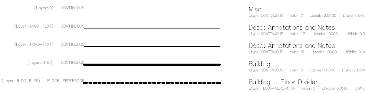
Example of line legend created
Notes:
The color, scale and other details written on the right in small letters can be deleted after the command completes, when you are preparing the legend for printing.
These details are shown to clarify the differences between line type categories.
Command Usage:
Besides inserting a line legend for printing, you can insert the legend to detect small differences in other properties (such as size or color bylayer, etc.) and correct the objects they belong to.
Tips:
When 2 or more categories appear identical and have the same other properties, their differences may be in decimal values for Scale or Weight, which is why they are shown in the legend.
In such cases, you should investigate why objects that should have the same properties are drawn slightly differently.
The command name ZYPGR is an abbreviation of "z YPomnima Grammon" (Line Legend).
Object Selection
Select as many objects as you want from the Drawing. (ALL = select all objects)
After selection, objects will be analyzed and categories will emerge according to line type, size, Layer, color, etc.
See the General Command 'Layer Selection'
You have the ability to choose in what order the various line categories will appear in the Legend.
Select the top-left point of the Line Legend to be created. After this selection, the Line Legend is drawn.
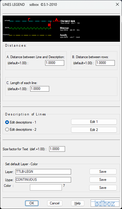
Inserting legend into drawing
Explanation configuration
Commands that open editing files: ZYPGR1, ZYPGR2
In these files you can write the explanation for each line type.
Line types in explanations are separated according to Linetype and color.
^ Back to topSelection - Configuration ZVFE
Opens a tab where you can view and edit the files that participate in various commands.
You can also select which file category each command will read when executed.
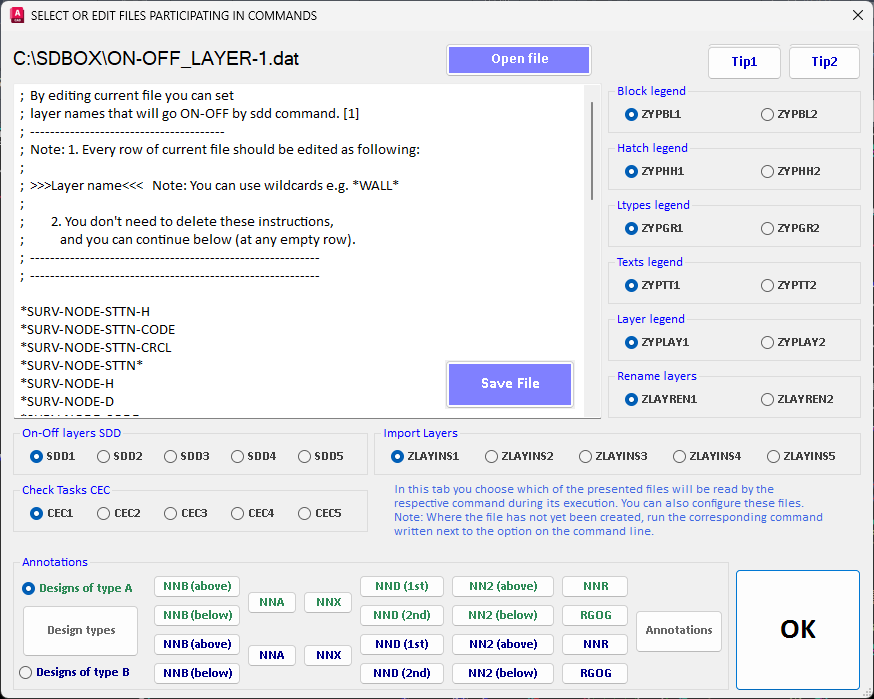
Command files configuration interface
^ Back to topEditing - 1,2 ZYPGR1, 2
Select which of the 2 available files the ZYPGR command will read during execution to write the correct explanation text according to Linetype name.
By typing ZYPGR1 or ZYPGR2 you define which file the command will read (1 or 2) accordingly, and you can also edit it if you want.
During Line Legend insertion, the explanations you have registered in the files of this command are written in the Drawing.
You can do the same by running the above ZVFE command.
File creation / editing
If you run the command for the first time and no file exists yet, the above message appears.

First execution message
ZYPGR1: Creates and updates file //SDBOX/YPOMNHMA_GRAMMON1.dat
ZYPGR2: Creates and updates file //SDBOX/YPOMNHMA_GRAMMON2.dat
Each time you run one of the above commands, the corresponding .dat file is set as default and the ZYPGR command searches for explanations in it.
If you don't run either of the 2, then YPOMNHMA_GRAMMON1.dat is set as default.
Esc or No: The command ends and file //SDBOX/YPOMNHMA_GRAMMON2.dat is set as the one that the ZYPGR command (Line Legend) will read.
Yes: Again the above file is set as default and the command continues by opening it for editing.
Adding explanations
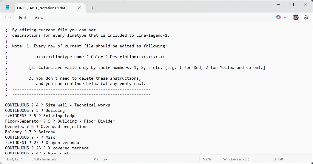
Adding new explanations
If the explanation file is empty then it opens automatically for adding explanations.
Each line of the explanation file is as follows:
Linetype ? Color ? ...explanation text
e.g. For drawing lines that are on Layer "Hidden" and have Linetype "DASHED", have color 5, you want the phrase "Hidden Edges" to be written as explanation in the Legend, then you must add the following line to the file:
DASHED ? 5 ? Hidden Edges
When you run the ZYPGR command and select such lines in the Line Legend, it will appear:
(Layer: Hidden) DASHED   -----------   Hidden Edges
                               Ltype: DASHED  color: 5   LtScale: 1.0
Notes:
As mentioned above, when you reach the point where the explanation files are fully defined, then you use the ZYPGR1 and ZYPGR2 commands only to determine which file the ZYPGR command will read.
That is, when asked if you "want to open the file" by pressing No or Esc.
Command Usage:
Whenever you want to configure the explanation file or define which file the ZYPGR command will read for explanations.
Tips:
To create and configure the explanation files for the first times, it is recommended to export from a typical drawing for you the Linetypes with the ZGRLIST command or detailed characteristics with ZGRLS.
From the files that open with the above commands you can copy the Linetypes and Color to file "YPOMNHMA_GRAMMON1.DAT" or "YPOMNHMA_GRAMMON2.DAT".
Drawing Line List ZGRLIST
Opens a Notepad file containing a List with the names of Linetypes contained in the Drawing.
The file is always \\SDBOX\LTYPES_LIST.dat and all Linetype Names that have been defined in the Drawing are exported.
You can, among others, use this command to copy the Linetype names to the Explanation files and then complete the descriptions.

Linetypes List from drawing
^ Back to topDetailed Line List ZGRLS
Opens a file of your choice containing a detailed List (Ltype, Layer, Color, Scale, etc.) of the objects (Line, Pline, etc.) that you select in the Drawing.
You select export file and number of objects from the Drawing which are analyzed, divided into categories and each category's elements (Ltype, Layer, Color, Scale, etc.) are exported to the file.
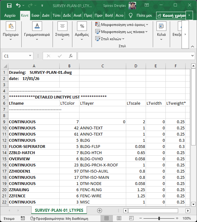
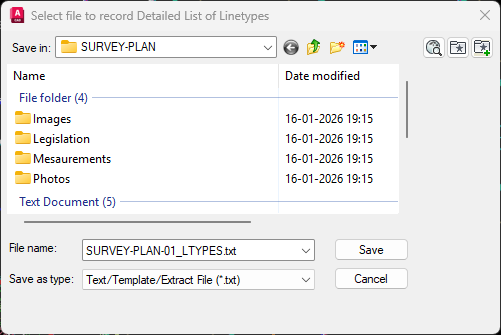
Export file selection
Select file for exporting the elements of each category of objects you select in the Drawing.
Object selection from drawing
Detailed object selection with filters
You have the ability to choose in what order the various line categories will be written to the file.
Notes:
When you export line elements of the Drawing to MsWord (*.doc) or Excel (*.xls) files, the export files are in "Tab delimited text (txt)" format. If you want, after opening the file you can save it in normal doc or xls format.
Command Usage:
After exporting the Line elements to a txt file, you can copy the Linetypes and Color and paste them into the ZYPGR1 and ZYPGR2 command files, completing explanations for the Line Legend.
Tips:
When 2 or more categories appear identical and have identical other elements, then their differences are in the decimals of numbers for Scale, Width, or Weight, and that's why they appear in the file.
If you have such a case, you should investigate why objects that you want with identical characteristics are drawn slightly differently from each other.