Drawing Views
SDBox Design Software - Command guide for creation and management of drawing Views in Model and Layout
View Creation ZVM
Move on screen with the mouse and save various drawing areas as display type (View) which you can recall with the ZVV command.
The command is used when you have areas in the same Drawing at long distance from each other so you can move from one area to another easily.
The same use is when you have e.g. details in the Drawing and with this command you save them with characteristic names and then move from one to another with the ZVV command.
This message reminds you of the command procedure.
Adjust the screen as you want and name the View here or RETURN=EXIT :
Move on screen only with the mouse and the middle wheel (not with zoom window etc.) and as long as the area you want appears on screen write the name of the View that will be saved.
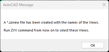
View creation example
Adjust the screen as you want and name the View here or RETURN=EXIT :
The procedure continues in the same way for as many Views as you want.
Each time you run the command new Views are added to the previous ones.
Note:
View names are saved also in file **.zzview in the same folder as the Drawing.
If you change the Drawing name then you must also change the name of this file accordingly to use these Views with the ZVV command.
Drawing Views ZVV
Recall the drawing Views you have created with the ZVM command.
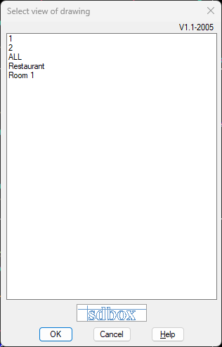
Drawing Views selection interface
Select with double click or OK the View you want and the screen zooms to this area of the Drawing.
----> Drawing Views.. OK.......ZVV <----
Import View from another Drawing ZZVVIM
Import into the present drawing Views that you have created in another Drawing with the ZVM, ZVBL and ZVK commands.
From the other Drawing you select, the Views it has are imported into your Drawing and the files of the corresponding commands are updated simultaneously.
^ Back to topAlign Vports in Model ZVF
Define 2 Vports in the Model which will be aligned in X or Y between them when you execute the ZVFF command.
An example use of the command is during drawing a Section or Elevation where 2 Vports are used, one for the Plan and one for the Section or Elevation.
Align 2 Vports in X or Y ? X/Y <X> :
Select whether alignment will be on X or Y axis. If you type X:
Select a point in the Vport from which Vport you will determine the "zoom" and the X position for the next one.
Select a point in the Vport which will follow the previous one according to the above when you execute the ZVFF command.
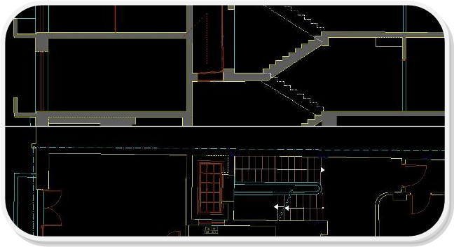
Vport alignment example
^ Back to topAlign Vports with previous selections ZVFF
Alignment of Vports that you have defined with the ZVF command.
When you type this command the 2 Vports that have been defined with the ZVF command are aligned with same "zoom" and same position in X or in Y.
For example in the above command ZVF example if you are in the following state:
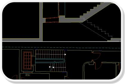
Before alignment
And you type ZVFF then you will have the following alignment result of the 2 Drawings between them:
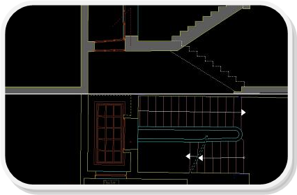
After alignment
^ Back to topNew ViewPort in Layout with center in Model ZVPLK
Define the rectangle of the new Viewport in Layout and select in Model its center and display scale. You can also annotate the Center coordinates in Layout.
The command must start from Layout.
Details: Layer Selection
Give the 1st point of the frame of the new Vport in Layout.
Give the 2nd and last point of the frame of the new Vport in Layout.
You are transferred to Model and either select a point on screen that will be the Center of the new Vport, or select a Block whose insertion coordinates will be the Center.
In both cases you have the possibility, subsequently, to annotate the Center coordinates at the edge of the new Vport.
If you select Block then you also have the possibility to annotate the Attribute values.
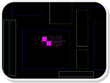
Model view
If you want display in real dimensions of the Drawing then give 1.000
Then you select whether to annotate the Center coordinates and the Block Attribute values.
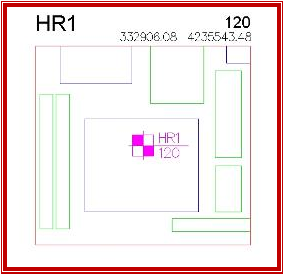 ^ Back to top
New ViewPort from Model in same coordinates ZVPMC
Define an area in Model which is displayed in Layout with Viewport in the same coordinates.
The command must start from Layout.
Details: Layer Selection
Give the 1st point of the frame of the new Vport in Model.
Give the 2nd and last point of the area in Model.

Area selection in Model
In Layout the frame of the new Vport will be drawn anyway.
If you want display in real dimensions of the Drawing then give 1.000
Then the new Vport is drawn in Layout in the same coordinates as the points you selected in Model.
^ Back to topZero rotation Vport VV0
The Viewports in Layout that you select are set to have the rotation you give in their display.
If you want zero rotation then give rotation 0.00
^ Back to top