Witnessing (Control Points / Ties)
SDBOX CAD add-on “ workflow for producing a witnessing sheet in a Layout, using viewports, blocks and automated annotations.
Overview
This workflow helps you document and witness survey control points and reference features (e.g., stations, trigonometric points, manholes, corners of walls/buildings, etc.) in a clear, printable sheet.
The standard output is created in a Layout and consists of:
- A predefined Witnessing Frame (title and table fields)
- Up to four (4) witnessing viewports with point labels and descriptions
- Witnessing lines (usually dashed) drawn on a dedicated layer
- Witnessing dimensions written as plain text and computed with a scale multiplier
Recommended workflow
- Insert the witnessing frame in the Layout (ZTITLOI).
- Create each witnessing viewport and fill the block attributes (ZVPLK).
- Draw the witnessing lines (LD1).
- Add witnessing dimensions (ZDEXASF).
Tip
Always start these commands from the Layout when the sheet is intended for printing. This ensures consistent viewport scaling and correct annotations.
Insert Witnessing Frame ZTITLOI
Inserts the witnessing sheet frame in a Layout and prepares the space where new viewports, dimensions and the table will be produced.
What it does
- Inserts the predefined witnessing frame in the current Layout.
- Provides fields for project data (filled once, then reused).
- Defines the area where the witnessing viewports and table entries will be created.
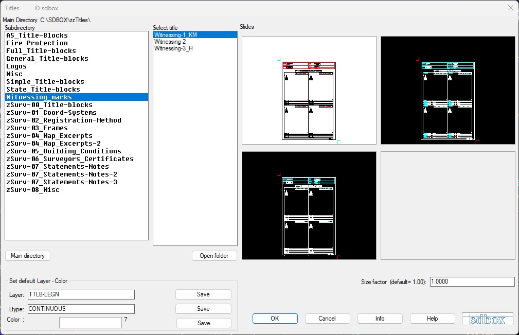
Witnessing frame inserted in a Layout.
Notes
The Drawing No. field typically refers to the sheet/page number within your project set.
For more information about titles and title-block insertion, see: Titles & Legends.
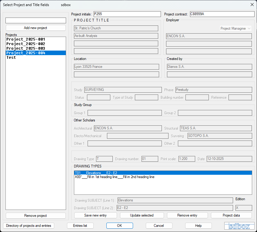
Project data and frame fields (entered once and reused).
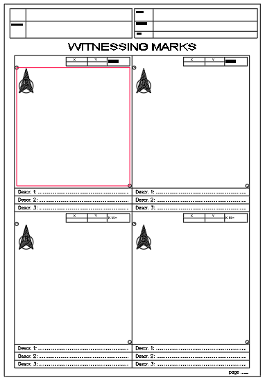
Witnessing sheet prepared for up to four (4) witnessing viewports.
^ Back to topWitnessing Viewports (Survey Points) ZVPLK
Creates a new witnessing viewport in the Layout, then switches to Model space to select the point/block and define the view center and scale.
Steps
- Start the command from the Layout.
- Define the rectangle of the new Viewport using the two reference points already present in the witnessing frame.
- The command switches to Model: select the control point Block.
- Set the viewport center and display scale so the control point and surrounding reference features are clearly visible.
- Confirm or fill the required attributes (e.g., code/ID, description, chainage where applicable).
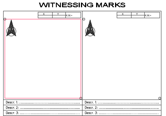
Defining the new viewport rectangle in the Layout.
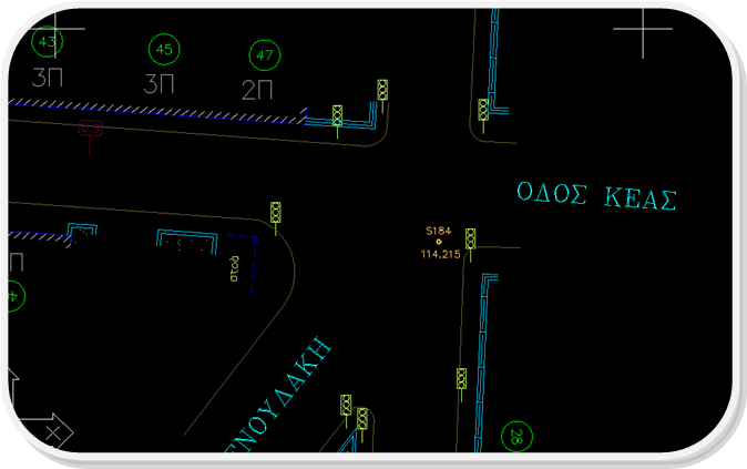
Selecting the point/block in Model space.
Notes
The suggested viewport scale depends on the drawing and the density of features. In many cases a scale around 1:500 provides a readable result.
For detailed information about viewports and this workflow, see: Viewports in Layout (ZVPLK).
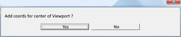
Witnessing titles/attributes filled automatically.
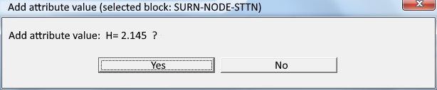
Attributes for the witnessing sheet (example).
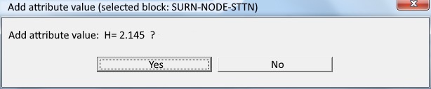
Additional attribute lines (example).
Tip
The second attribute line can be used to store and print Chainage (or any project-specific reference) automatically, if your sheet template is configured accordingly.
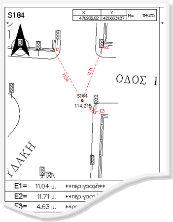
Example of an automatically created witnessing viewport.
After the viewport is created and the frame fields are filled, continue with witnessing lines and witnessing dimensions.
^ Back to topWitnessing Dimensions ZDEXASF
Writes witnessing dimensions as plain text using user-selected points and a suggested multiplier, so the printed dimension values match the viewport scale.
How scaling works
If your witnessing viewport is at scale 1:1500, a typical multiplier is:
1 / 1500 = 0.000667
This ensures that distances measured inside the magnified viewport are reported as real-world distances on the printed sheet.
Notes
The second point of each witnessing dimension can carry a code/number that is also reported automatically in the table, depending on your template setup.
For the full command documentation, see: Dimensions (ZDEXASF).
Witnessing Lines LD1
Draws dashed witnessing lines on a layer of your choice (recommended: Exasfaliseis), connecting the control point to the witnessed features.
Usage
- Draw the lines as clean, readable ties from the point to the reference features.
- Keep the linework consistent across all witnessing viewports for easy review and printing.
Notes
For best results, use a dedicated layer (often named Exasfaliseis) and a dashed linetype suitable for plotting.
More details about line drawing conventions: Drawing lines.
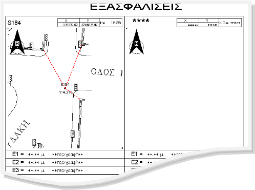
Example of witnessing lines drawn in the suggested layer.
Tip
The only remaining manual input is usually the feature description. Keep descriptions short and unambiguous (CAD plotting friendly).