Legends - Titles
SDBox Design Software – Insert legends, titles, notes, headers, and manage project databases in CAD drawings
Insert Title block ZTITLOI
Select the type of Title to insert into the drawing. Then a Projects dialog opens where you can configure fields for each project or drawing, export a drawing list, etc.
The command, besides inserting a Title, also serves as a project database where project data and all created Drawings are stored.
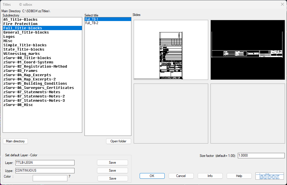
Title selection dialog with categories and preview
Select category and title
Select a Category and the Title you want. Fields contained in the Title are shown in red. These fields are keywords and will be active in the next dialog that opens. For keywords you can add to your Titles see the command TCDS.
Layer selection
Details: Layer Selection.
Insertion point
Choose the point where the Title will be placed in the Drawing.
After placement, the following dialog opens which has active all fields that exist in the Title. (You can open and configure this dialog outside the command with ZZBASE.)
You can add a new Project, add or modify Drawings in an existing one, remove a Drawing or Project, export a Drawing List, etc.
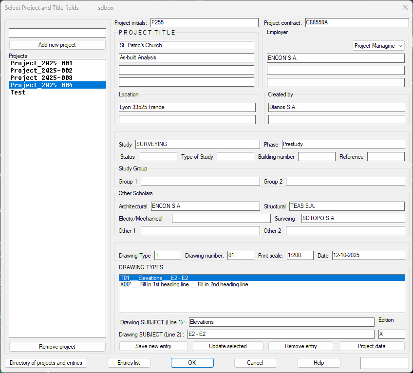
Project and drawing management dialog with fields and list
Project selection or creation
Enter the name of the New Project and add it to the List, or select a Project from the existing ones listed.
When the dialog opens, the Project you selected in the last use of the command in any Drawing is suggested.
The Project you select contains the Drawings displayed in the right part of the Dialog.
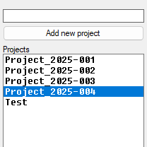
Project list and new project entry
Fill in fields
Fill in the corresponding fields that are enabled, i.e., existed as keywords in the Title you inserted.
For keywords you can add to Titles so that the corresponding fields become active, see the command TCDS.
Entries in each field can be the same for all Drawings (with only Drawing Titles, Scale, and date changing) or all can be different in each Drawing.
The first time you fill in the Project fields you must create a “New Drawing” in the lower part of the dialog for them to be saved.
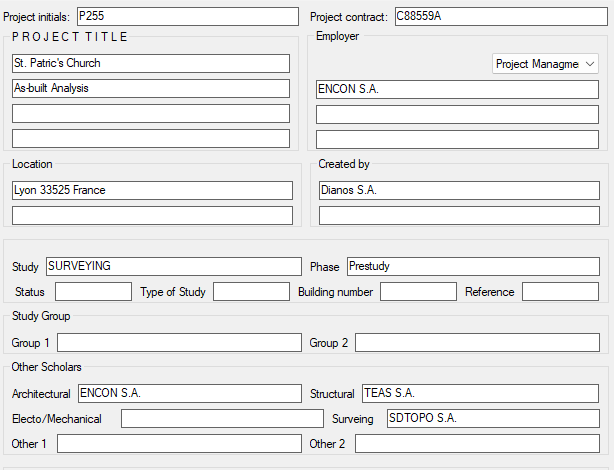
Fields for project data entry
Drawing management
New Drawing: Saves entries in all dialog fields. Each new Drawing can have all dialog fields the same except some from Type, number, or subject of the Drawing.
Remove Drawing: Removes whichever Drawing you have selected from the Drawing List.
Save: Saves entries in all dialog fields for whichever Drawing you have selected from the Drawing List.
Project File: Opens the project file read by the command. You can use this command to make bulk changes to all Drawings.
Each line of the file records the code of each field and the entries you have entered.
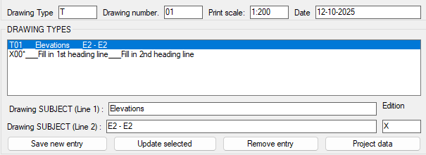
Drawing list and management buttons (New, Remove, Save, etc.)
Project file example
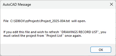
Example of a project data file
Project and drawing directory
Note:
The command ends, fields are not inserted into the Title, and opens (via Windows) the folder where the project database files and Drawings are located. This folder can also be network shared.
Details: ERGACHDIR.
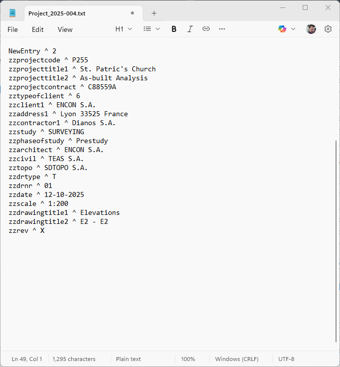
Project and drawing directory structure
Drawing list export
Note:
The command ends, fields are not inserted into the Title, and opens a file containing the basic project data and a Drawing List that you can format.
Drawing list exported to a file

Example of a drawing list with project data
Title update after selection
If you select a Drawing and press OK, the Title you inserted at the beginning is updated:
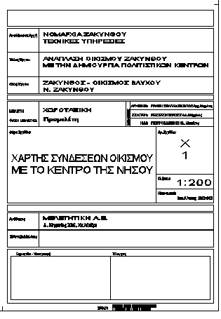
Title block with fields filled after dialog confirmation
Tips:
If a Project has many Drawings, it is recommended after inserting the 1st Title to format the initial Title (in the example General_Title-1.dwg where you can set other fonts or alignment types like Fit, left, etc.), save it with another name, and insert that one into the remaining Drawings of the Project.
Change Title Directory TITLOICHDIR
Defines the path where the folders with Title files (dwg) are located. The command reads this path and opens a dialog with Titles for insertion. The path can also be network shared.
You define a new address for the folder zzTitloi which contains the subfolders – categories of Titles.
You can set the Title library to be read from a shared folder on the network so that many users can use and enrich the same library.
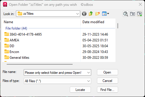
Dialog to select the title library folder
How to change the library path
To change the address of the Title library you simply need to open (with the above window) the folder zzTitloi wherever you have placed it.
Once you open the folder, without selecting anything else with the mouse, and press Save, the address is recorded and this is set as the library address used by the command ZTITLOI.
In the File Name position, “Do not change anything here!” is written to remind you that after opening the folder zzTitloi you do not need to select any file or anything else, just press Save.
Tips:
You can change the ZTITLOI address as many times as you want, even within the same Drawing.
The general folder zzTitloi can also have another name of your preference.
You can open the zzTitloi folder from the ZTITLOI command dialog with the “General address” button.
Change Projects Directory ERGACHDIR
Defines the address of the file zzErga.txt which contains the names of Projects participating in the database. Files with each Project's fields are created at this address. You can also set a network address.
To change the address of the project database, you simply need to open (with the above window) the file zzERGA.txt wherever you have placed it.
Once you open the file, the address is recorded and this is set as the Projects address used by the command ZTITLOI.
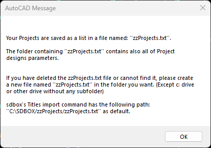
Dialog to select the projects database file
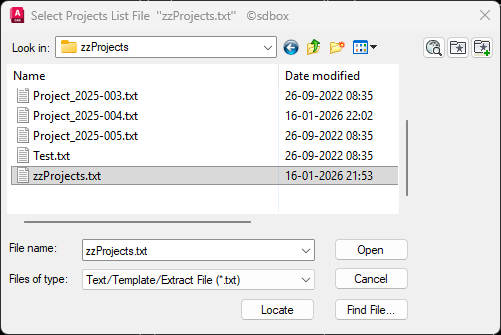
Example content of the projects database file
Tips:
You can change the address of the file zzERGA.txt as many times as you want.
You can open the project database folder from the ZTITLOI command dialog with the “Projects and Drawings address” button.
Field Codes for Titles TCDS
If you are designing a new Title drawing or modifying an existing one, you can add fields by copying codes from the opened dialog and pasting them into the corresponding Text on screen.
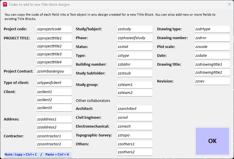
Dialog listing all available field codes for titles
Using field codes
You can format your own Title drawing (dwg) as you like and in the positions of the corresponding fields place texts (Text or Mtext) that record the above codes.
When inserting a Title (with the command ZTITLOI) when the dialog opens and you fill in the fields, the corresponding texts on screen will be replaced with the entries.
Notes:
Field codes are case-sensitive and must be placed exactly as shown in the dialog.
You can combine multiple codes in a single text line.
If a code is not recognized, the field will remain empty in the inserted title.
Projects Database ZZBASE
Opens the Titles and Drawings dialog which you can correct and complete for the next use of the ZTITLOI command or for archiving project data.
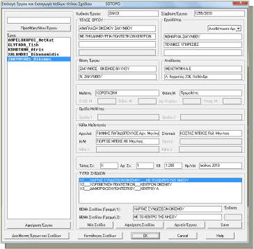
Projects database management dialog
You can add a new Project or a new Drawing to an existing Project, or format the existing ones.
For details see the command ZTITLOI above.
Command Usage:
Use this command to review, edit, or archive project data without inserting a title into a drawing.
It is also useful for batch updates across multiple drawings in the same project.
Insert Short Title (Stamp) PHSTI2
Inserts 5 lines of Text (Project, Client, location, Date, Study type, Drawing type, scale) and a Logo (small). The phrases inserted remain in AutoCAD's memory for insertion into the same or another Drawing.
It is a quick way to insert a stamp with the drawing data, and if you have many similar Drawings you are informed by the command what you wrote in the last one.
Details: See more.
Tips:
You can modify the default stamp by editing the drawing logotipo_mikro.dwg (see command ZSTI).
The stamp is inserted at the current text height and layer settings.
Edit Short Designation ZSTI
Opens the drawing logotipo_mikro.dwg that participates in the PHSTI2 command, and you can edit and complete it so that it is inserted ready into every drawing automatically.
This command allows you to customize the small logo and text layout used by PHSTI2.
After editing, save the drawing in the same location with the same name.
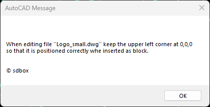
Editing the small logo drawing used in PHSTI2
^ Back to topNotes - Headers YYTT
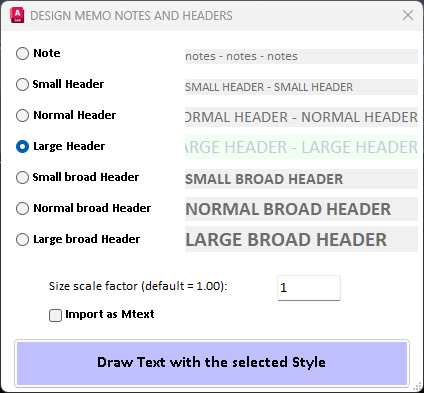
Opens a dialog from which you select the type of text (Notes, Small-Medium-Large Title, Small-Medium-Large Wide Title) to insert into the drawing to determine the size and font.
Text heights are proportional to the print scale.
Dialog for selecting text type and size
Steps
- Select the type you want. Based on the selection, font and text size will be determined.
- You can also give a scaling factor from the default letter heights of the command.
- Enter the LAYER for the selected text type.
- Pick the starting point for the text.
- Specify the text direction (horizontal by default).
- Type the text lines.
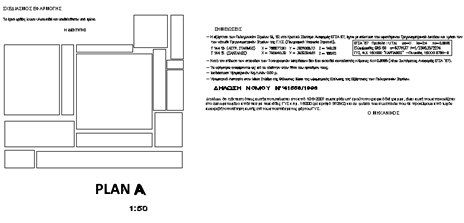
Example of inserting a wide medium title
Resulting text inserted in the drawing
Command Usage:
Use this command for consistent annotation and title blocks across drawings, especially when working with multiple scales.
Line Types Legend ZYPGR
Legend of line types of linear objects selected from the Drawing.
A list is created on screen (in legend form) showing the various line types you have selected based on Linetype, Scale, Layer, Color, etc., and provides an explanation for each distinct type: Line, Pline, Mline, Xline, Ray, Spline, Arc, Circle, Ellipse, 3D Face, and Region in the drawing.
Text Height is set automatically according to the print scale.
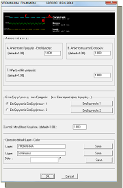
Example of a line types legend
Details: See full documentation.
^ Back to topBlock Symbols Legend ZYPBL
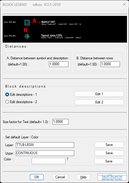
Legend of Block types selected from the Drawing.
A list is created on screen (in legend form) showing the various Block types you have selected based on Block Name, size, Layer, Color, etc., and an explanation for each Block.
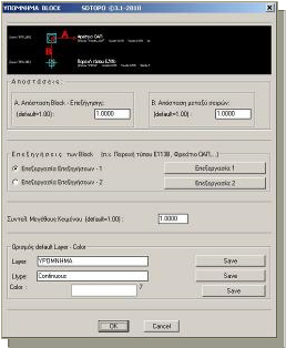
Example of a block symbols legend
Details: See full documentation.
^ Back to topHatch Legend ZYPHH
Legend of Hatch types selected from the Drawing.
A list is created on screen (in legend form) showing the various Hatch types you have selected based on Type, Scale, Layer, Color, etc., and an explanation for each line.
The Text Height of texts is set automatically according to the print scale. Each Hatch is drawn as the corresponding ones in the Drawing.
Example of a hatch patterns legend
Details: See full documentation.
^ Back to topText Types Legend ZYPTT
Legend of Text, Mtext, and Rtext types selected from the Drawing.
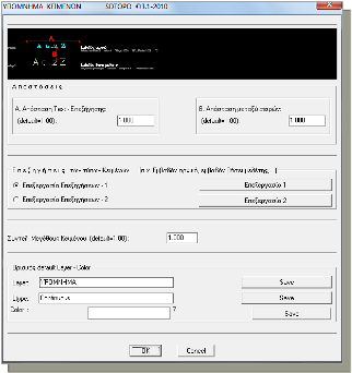
A list is created on screen (in legend form) showing the various text types existing in the Drawing based on TextStyle, Color, size, Layer, etc., and explanations that you have entered in a file with the commands ZYPTT1 or ZYPTT2.
It usually serves cases where drawing texts are organized with different colors and Text Styles per category.
Example of a text types legend
Details: See full documentation.
^ Back to topLayer Legend ZYPLAY
Layer legend with explanations and categorization of Drawing objects.
A list is created on screen (in legend form) showing the elements of the Layers that exist in the Drawing.
For each Layer the following are displayed: name, explanation, the types of objects it contains, and the various color and linetype.
The command is used either during electronic drawing delivery where you explain for each Layer what it contains and its meaning, or to have an overview of the objects existing in each Layer.
Details: See full documentation.
^ Back to topWindow-Door Legend YPPP
For openings where you have drawn a tag with the commands SPART (for window types) or SPORT (for door types), you can add a legend to the drawing with predefined explanations for the type of openings.
The explanations of the opening types are defined in a file (created with the command PARPO1) and you can use them in any Drawing.
Details: See full documentation.
Command Usage:
This legend is particularly useful in architectural drawings to provide a clear key for window and door types used in the project.