AutoCAD Dimensions
SDBox Design Software - Command guide for dimension creation and management in CAD drawings
Dimension Type Selection ZDDAS
Selection of AutoCAD dimension type with formatting capabilities for decimals, units, size, factors, etc.
Dimensions are drawn in size proportional to the drawing scale.
Dimension symbol for scales 1:1 up to 1:100:
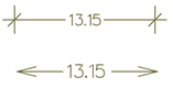
Dimension symbol for scales 1:1 to 1:100
Dimension symbol for scales larger than 1:100:
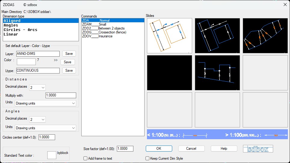
Dimension symbol for scales larger than 1:100
Layer selection for dimensions:
See the General Command 'Layer Selection'

Command Operation
You select one of the 17 AutoCAD-type dimension commands presented below.
The settings you make in the above tab are saved and suggested in each new use of the command in any Drawing.
Note:
If you have already executed any of the dimension commands and have made changes to the Dimension Style in AutoCAD, then to keep these changes (and not revert to default settings in what you have drawn) select "Draw in Current Dim Style".
At the end of each command you are informed of the number of dimensions added to the Drawing.
^ Back to topLinear Dimensions (Aligned/Linear) ZDA, ZDAM, ZDL, ZDLM, ZDOV
These commands function similarly to the corresponding AutoCAD ones with the following options:
- Repeated Dimensioning.
- Object Selection.
- Continuous Dimensioning.
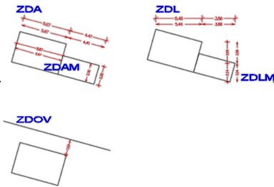
Linear dimension example
Command Details
- ZDA DimAligned Normal Internal-External: Aligned type with normal letter height.
- ZDAM DimAligned Small: Aligned type with smaller letter height.
- ZDL DimLinear Normal Internal-External: Linear type with normal letter height.
- ZDLM DimLinear Small: Linear type with smaller letter height.
- ZDOV DimLinear Insurances (circle - arrow): Aligned type with normal letter height, where one end has a circle and the other an arrow.
Below is an example for ZDA. The others work similarly.
Command Steps
Give the Layer for 'Dimensions' :
Details: Layer Selection
Select the 1st point for the 1st dimension. If you right-click or press Enter you can select an object to be dimensioned automatically.
Give the 2nd point or select object.
The dimension has been drawn and you place it in its final position.
Give the next dimension. If you don't want another dimension you can give "No" or press Enter twice or right-click.
If you press Yes or right-click then a dimension continuous to the last one you placed is temporarily drawn.
Give the 2nd point of the continued dimension or with right-click or Enter select another dimension from which you want to continue.
Tip:
If from the beginning you want to reach this point (of continuous dimension) you can give Enter or right-click in all questions.
...between 2 objects ZDD2
Select 2 objects on screen and then dimensions are drawn between them at the distances you specify.
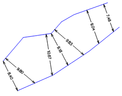
Dimension between 2 objects
For the 2 objects you can select Lines, *Polylines, Arcs, Splines, Circles, Ellipses.
Dimensions start from the 1st object perpendicular to the 2nd.
They are drawn along the 1st at a distance you give with a number or with a dimension on screen.
^ Back to top...at intersection with imaginary line ZDDG
Give an imaginary line and dimensions are drawn at the intersection points of the imaginary line with the objects it crosses.
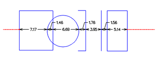
Dimension at intersection with imaginary line
Give the 2 points of the imaginary line and dimensions are drawn automatically at any points where objects intersect.
^ Back to topAngle of 3 points ZDW
Select the center of the angle and then the 2 ends. Then select whether to draw the internal or supplementary angle.
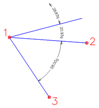
Angle of 3 points
Select with the mouse the 3 points of the angle with first the center.
Move with the mouse and define whether the internal or supplementary will be drawn.
You can then draw continuous angles at subsequent points.
^ Back to topAngle of selected objects ZDWS
Select objects and the angle between them is drawn.
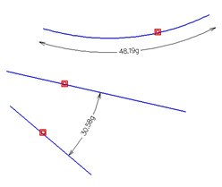
Angle of selected objects
Select with the mouse the objects for angle between them.
Move with the mouse and define whether the internal or supplementary will be drawn.
For objects you can select Line, Pline, Arc, Circle.
If you select Arc then the angle from the center to the ends of the arc is drawn.
If you select Circle then you also give a 2nd point for which the angle from the Center is drawn.
^ Back to topAzimuth of 2 points ZDWA
Select 2 points between which the Azimuth is drawn.
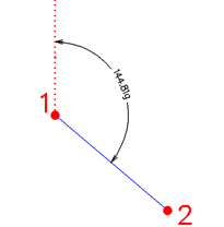
Azimuth of 2 points
Select with the mouse the 2 points for which the Azimuth will be calculated.
Move with the mouse and define whether the internal or supplementary angle will be drawn.
Continue with next points for Azimuth.
^ Back to topRadius ZDRAD
Radius annotation of selected arc or circle.
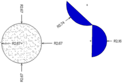
Radius dimension
Select the circle or arc and define the position of the radius annotation internally or externally.
Continue with the next circle or arc.
The letter "R" is added at the beginning of the radius length annotation.
^ Back to topDiameter ZDDIAM
Diameter annotation of selected arc or circle.
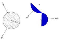
Diameter dimension
Select the circle or arc and define the position of the diameter annotation internally or externally.
Continue with the next circle or arc.
The symbol "O" is added at the beginning of the diameter length annotation.
^ Back to topRadius of selected objects ZDRADS
Simultaneous radius annotation of selected arcs or circles.
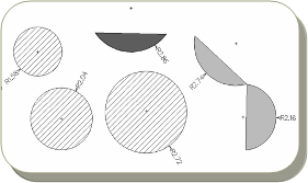
Radius of selected objects
Select, via filters, as many circles and arcs as you want.
The radii are drawn automatically in those you selected.
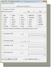
Object selection with filters
^ Back to topDiameter of selected objects ZDDIAMS
Simultaneous diameter annotation of selected arcs or circles.
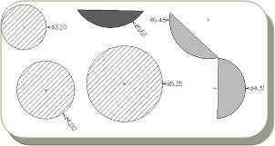
Diameter of selected objects
Select, via filters, as many circles and arcs as you want.
The diameters are drawn automatically in those you selected.
Object selection with filters
^ Back to topCenter of selected objects ZDCS
Simultaneous center annotation of selected arcs or circles.
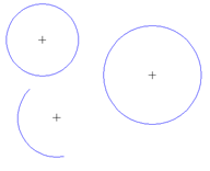
Center of selected objects
Select, via filters, as many circles and arcs as you want.
The centers are drawn automatically in those you selected.
Object selection with filters
^ Back to topArc Length ZDARC
Dimension annotation with the length of selected arc.
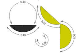
Arc length dimension
Select the arc for length calculation.
Move with the mouse and define whether the length of the drawn arc or the length of the remaining imaginary circle will be drawn.
Continue with the selection of the next arc.
^ Back to topFind Dimensions with non-real value ZCDIM
Red circles are drawn on those of the selected dimensions (AutoCAD type) that do not have real value but write something else.
Select, via filters, the dimensions you want to check.
In those where the real value is not found and something else is written, a circle is drawn on Layer "z_Diastaseis_No-True-Value".
You can edit these dimensions with the DDE command.
Object selection with filters
^ Back to topSimple Text Dimension Selection ZDDAT
Selection of simple Text dimension type with formatting capabilities for decimals, units, size, factors, etc.
Dimensions are drawn in size proportional to the drawing scale.
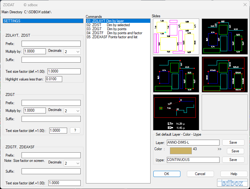
Simple Text dimension selection interface
Layer selection for dimensions:
See the General Command 'Layer Selection'

Command Operation
You select one of the 5 simple Text dimension commands presented below.
The settings you make in the above tab are saved and suggested in each new use of the command in any Drawing.
At the end of each command you are informed of the number of texts added to the Drawing as dimensions.
^ Back to topDimensioning by Layer ZDLAYT
Dimension annotation (simple Text) of all objects that are on the same Layer.
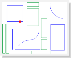
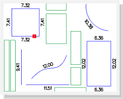
Dimensioning by Layer examples
Give the Layer of 'Layer dimensioning' :
Give the Layer on which the dimension texts will be drawn. Details
Select on screen an object which belongs to the Layer you wish to dimension.
Then side length dimensions for Lines, Plines and total length for Splines and Arcs will be automatically added to all objects that have the same Layer as the one you selected.
Note:
In the command tab of ZDDAT you can also set a minimum value, where dimensions smaller than this value are marked in the Drawing and moved to Layer z_Dim-Lathos.
Dimensioning of selected objects ZDST
Dimension annotation (simple Text) of all objects selected by the user.
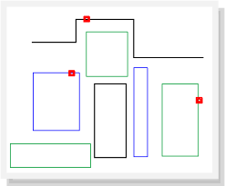
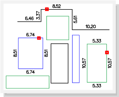
Dimensioning of selected objects examples
Give the Layer of 'selected dimensioning' :
Give the Layer on which the dimension texts will be drawn. Details
Select, via filters, the characteristics of the objects to be dimensioned or select objects directly on screen.
Then side length dimensions for Lines, Plines and total length for Splines and Arcs will be automatically added to all objects you selected.
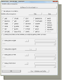
Object selection with filters
Note:
In the command tab of ZDDAT you can also set a minimum value, where dimensions smaller than this value are marked in the Drawing and moved to Layer z_Dim-Lathos.
Dimensioning with points ZDGT
Dimension annotation (simple Text) with points that the user selects on objects or not.
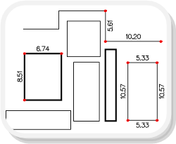
Dimensioning with points
Give the Layer of 'dimensioning' :
Give the Layer on which the dimension texts will be drawn. Details
Give on screen the 1st point for the 1st dimension.
Give on screen the 2nd point for the 1st dimension or press Enter for new Start.
Give on screen the 3rd point for the 2nd dimension or press Enter for new Start.
Continue like this for as many points as you want.
^ Back to topDimensioning with points and factor ZDGTF
Dimension annotation (simple Text) with points that the user selects and suggested multiplier each time.
While in the above command ZDGT you can enter a factor by which lengths will be multiplied (in the command tab of ZDDAT), in this command you are asked for a factor each time and you can also select Viewport (if you run the command in Layout) where depending on the Scale the corresponding factor is calculated so that dimensions are the real ones.
The command was created for cases where you want to change factor frequently and for cases where the points you select are in Viewport in Layout where if the Viewport does not have scale 1:1 then depending on the display scale the correct factor for annotation of real dimensions is calculated.
Otherwise the command functions like the previous ZDGT.
Note:
When you select Viewport (if you run the command in Layout) then depending on its scale such factor is suggested so that the real dimension is displayed on screen, provided that what the Viewport displays has been drawn 1:1.
Again you can not accept the suggested factor and give your own.
Insurances Dimensioning ZDEXASF
Dimension annotation (simple Text) with points that the user selects and suggested multiplier each time. At the 2nd point of each dimension a code is written and at the end you can add a table of distances.
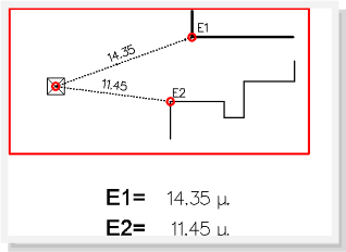
Insurances dimensioning
The command functions like the above ZDGTF with the difference that you can give prefix and numbering for each 2nd point of each dimension and that a Table with Codes and dimensions is added.
Note:
When you finish with the first two points then define new start if you want to give distance again from the 1st point.
Change Dimension Text DDE
Editing of contents, Texts (Text, Mtext), Attributes of a Block, dimension values (Dimensions) and Rtext.
The command was initially created for Acad 2000 with the purpose of being the same command that edits contents of Texts, Block and Dimension.
^ Back to topzzDistance ZDD
Repeated distances. Each of the distances is written in the Command Line. You can also type point codes.
The command functions like the corresponding AutoCAD one with the difference that successive distances are written in the command line and you are informed if you select 3D points.
^ Back to top