Line Design and Editing Commands
SDBox Design Software - Comprehensive tools for creating, modifying, and managing lines, polylines, arcs, and splines in CAD drawings
Introduction
Design and edit lines (Line, Pline, Arc, Circle...) with specialized CAD tools.
SDBox provides over 150 different line types for drawing Lines, Polylines, or Arcs with line type selection. During drawing, you can create points, type coordinates, input point sequences, and get informed about 3D points. The LineType Scale is set automatically according to the print scale.
Platform Support:
These commands work with AutoCAD 2010-20xx, BricsCAD, GstarCAD, and ZwCAD.
Drawing with Line Selection ZLL
Draw ~150 different line types for Line or Pline or Arc with line type selection.
During drawing you can create points, type coordinates, input point sequences, and get informed about 3D points. The LineType Scale is set automatically according to the print scale.
Features
- Select from approximately 150 pre-defined line types
- Automatic LineType Scale adjustment based on plot scale
- Point creation during drawing process
- Coordinate input via keyboard
- 3D point detection and notification
- Support for custom linetypes with letters
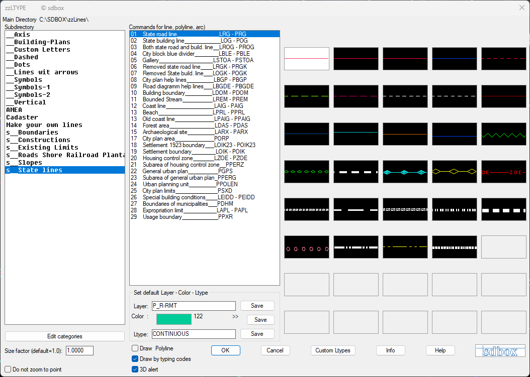
Line type selection dialog with custom options
Layer Selection:
You can choose the layer for new lines. Details about layer selection
Custom Linetypes:
You can define line types with letters of your choice. For example, for the letter A: ----- A ----- A -----
These are useful for specialized annotations and markings.
Point Creation During Drawing
You can select which Blocks participate in the command and which Attribute contains the codes you type during drawing. Details
3D Point Notification
If you select this option, during drawing you will be notified when selecting a point that doesn't have Z=0.00.
Point Creation Options
During drawing you have many point creation possibilities. Details
^ Back to topLines with Same Y or X at Both Ends GGY, GGX
Draw horizontal or vertical lines by fixing one coordinate value.
GGY: Draw lines with the same Y coordinate at both ends. You select or type the desired Y value, then select X coordinates to draw horizontal lines.
GGX: Draw lines with the same X coordinate at both ends. You select or type the desired X value, then select Y coordinates to draw vertical lines.
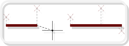
Creating horizontal lines with fixed Y coordinate
Write or select with point the Y: [E=options] <-20.5014>:
You can type the desired Y or type E for calculation options.
After selecting Y, you select points on screen and lines are drawn with X from each point and Y the selected value.
Practical Use:
This command is very useful when creating section or elevation drawings where multiple elements need to align horizontally or vertically.
Best Fit Line BLST
Draw the optimal straight line that passes as close as possible through selected points.
Select multiple points and the command calculates the line that best fits all selected points using regression analysis.
Select the 1st from points for median line:
Select points sequentially that will participate in the best fit line calculation. You can use Undo during the process.
After finishing, you're informed about the line properties: number of points, length, and maximum deviation.
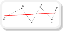
Best fit line through multiple points
Typical Applications:
- Finding centerlines from irregular measurements
- Aligning points for construction lines
- Creating reference lines from survey points
Rectangle with Sides and Direction ZDTT
Draw a rectangle at any orientation by specifying side lengths and direction.
Create rectangles by defining one side with two points (or one point and a distance), then specifying the perpendicular side length.
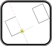
Creating oriented rectangles
Give 2 points (or 1 point and distance for the 2nd) for one side of the rectangle. After defining the first side, a temporary infinite line is drawn in perpendicular direction at the distance you gave for the first length.
You can select the 2nd point of the rectangle on this temporary line or give the length and it will be drawn automatically.
Workflow:
- Select first point of rectangle side
- Select second point or enter distance for first side
- Enter length of perpendicular side
- Rectangle is created at specified orientation
Rectangle with 4 Points ZR4
Draw a rectangle by selecting one point on each side.
Select four points (one on each side of the rectangle) and the command creates a rectangle that encloses all points.
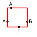
Creating rectangle from boundary points
This is useful when you have existing geometry that defines the boundaries of a rectangle and you want to create a clean rectangular shape around it.
Note:
The points don't need to be exactly on the corners - they can be anywhere on each side. The command calculates the rectangle that touches all four points.
Perpendicular to Line Point PP
Draw a perpendicular line from any point on an existing line.
Procedure: a. Select the side where the new line will be drawn, b. Select the point on existing line where perpendicular will start, c. Specify the perpendicular line length.
SIDE of new line? <ENTER=EXIT>:
POINT on existing? <ENTER=Undo>:
Give number or distance 'LENGTH'? <ENTER = free length>:
- Select the side where the perpendicular line will be drawn
- Select any point on an existing line from which the perpendicular will be drawn
- Enter the length of the perpendicular line (by typing a number or dimensioning on screen)
If you press Enter at the length prompt, the length is defined from the projection of the first point you selected for the side to the existing line.
Common Uses:
- Creating perpendicular construction lines
- Drawing offsets from existing geometry
- Setting up measurement points perpendicular to features
3D Perpendicular to Line 3DPP
Draw a 3D perpendicular line from any point on an existing line with Z coordinate control.
Procedure: a. Select the side where the new line will be drawn, b. Select the point on existing line where perpendicular will start, c. Specify the perpendicular line length, d. Specify Z coordinate for the perpendicular line.
Same as PP command with the addition that you can specify Z coordinate for the new line. This is essential for 3D modeling work where lines need to extend in three dimensions.
3D Modeling:
Use this command when working with 3D terrain models, structural elements, or any application where lines need to extend vertically from planar geometry.
Extend to Point ZEX
Extend Lines, Polylines, Arcs, etc. to any point selected on screen.
Select any point on screen (not necessarily on an object) and extend selected Lines, Polylines, Arcs, etc. to that point.
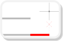
Extending multiple lines to a common point
This is different from standard AutoCAD EXTEND command as it extends to an arbitrary point rather than to a boundary object.
When to Use:
- Extending multiple lines to meet at a common point
- Creating radial patterns from a center point
- Aligning object ends to a reference point
Cut Line Segment ZCT
Cut a segment from Line, Polyline, Arc, etc. by selecting cut point and side to remove.
Select a cut point on a Line, Polyline, Arc, etc. and then select which side should be removed.
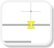
Cutting a segment from a line
This command provides a quick way to trim objects at specific points without needing to use the TRIM command with cutting edges.
Comparison with TRIM:
ZCT is faster for simple cuts where you know exactly where to cut and which side to remove, while TRIM is better for complex trimming with multiple boundaries.
Total Line Length GT
Set selected objects to a specific total length.
Enter a desired length (by number or dimension on screen) and then select objects that will acquire this total length.
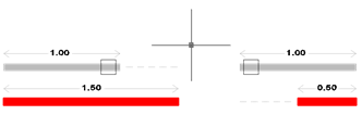
Setting multiple lines to the same total length
The length you enter each time is saved and suggested in each new use of the command.
This command is a specialized use of the AutoCAD LENGTHEN (Total) command with enhanced selection and memory features.
Applications:
- Standardizing multiple lines to the same length
- Preparing objects for array or pattern operations
- Creating uniform construction geometry
Extend Line GD
Extend selected objects by a specific delta length.
Enter a delta length (by number or dimension on screen) and then select objects that will be extended by this distance.
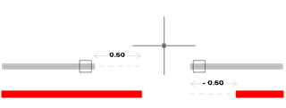
Extending lines by a specific distance
The delta length you enter each time is saved and suggested in each new use of the command.
This command is a specialized use of the AutoCAD LENGTHEN (Delta) command with enhanced selection and memory features.
Memory Feature:
The command remembers the last delta value used, making it efficient when extending multiple objects by the same amount in a drawing session.
Break at 1 Point Q1
Break an object into two parts at a selected point.
Select the object to be split into two, then select any point on screen whose projection on the object will be the break point.
This command is a specialized use of the AutoCAD BREAK command optimized for breaking at a single point rather than between two points.
Compared to Standard BREAK:
Standard BREAK requires selecting the object and then two break points. Q1 is faster when you just need to split an object at one location without removing any segment.
Measure on Multiple Objects ZMES
Simultaneously execute MEASURE command with points on multiple objects.
Place points at regular intervals on multiple selected objects in one operation.
Features:
- Select objects using filters
- Select insertion distance for points by dimension on screen or number
- Select Layer (existing or new) for point insertion
- Get informed about number of objects processed
At the end you're informed about how many of the initially selected objects had the command executed on them.
This command is a specialized use of the AutoCAD MEASURE command with batch processing capabilities.
Efficiency:
ZMES can process hundreds of objects simultaneously, saving significant time compared to using MEASURE on each object individually.
Join to Polyline PLL
Join selected objects into continuous Polylines using filters.
Select objects via filters that will be joined into unified Polylines.
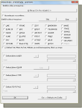
Object selection with filter options
After selecting objects to join into Polylines, you're informed about the results:
Filter Tab:
The filter selection tab can be dismissed with Esc if you want to continue the command without filters.
If you have a set of Layers containing objects you frequently use in the command, selecting them from the "Layer" field of the tab allows quick re-selection in each new use by typing "Y" and Enter when the tab opens.
Spline to Polyline S2P
Convert selected Splines to Polylines with control over point density between vertices.
Convert Splines to Polylines with ability to configure point density between vertices of the original Spline.
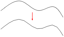
Converting Splines to Polylines
The command can be executed on many Splines simultaneously. Select Splines via filters.
At the end of the command, you can choose whether the original Splines remain in the Drawing or are deleted.
When to Convert:
- When you need to edit Spline vertices directly
- When exporting to formats that don't support Splines
- When you need consistent vertex spacing for measurements
Reverse Line/Polyline Direction PLCO
Reverse the drawing direction of Lines and Polylines.
Typically used in cases where subsequent commands relate to the starting point and drawing direction of objects.

Reversing Line/Polyline direction (before and after)
At the end of the command, a temporary point is drawn at the starting point of the object so you can visualize the drawing direction.
Important for:
- Hatch pattern direction
- Dimension placement
- Path-based operations (sweeps, arrays along path)
- Consistent flow in pipeline or electrical diagrams
Reverse Spline Direction SCO
Reverse the drawing direction of Splines.
Typically used in cases where subsequent commands relate to the starting point of objects.
The command can be executed on many Splines simultaneously. Select Splines via filters.
Applications:
- Preparing Splines for extrusion or sweep operations
- Aligning multiple Splines for surface creation
- Ensuring consistent flow direction in contour lines
Polyline to Arcs P2A
Convert Polyline to Curve Fit - redraw with only arcs between vertices.
Selected Polylines are redrawn only with arcs between vertices. They can be returned to their original form with the P2L command.
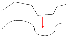
Converting Polyline to arc segments
The command can be executed on many Polylines simultaneously. Select Polylines via filters.
At the end of the command, you're informed about how many Polylines were processed.
Use Cases:
- Creating smooth curves from survey data
- Preparing geometry for CNC machining with arc interpolation
- Improving appearance of contour lines
Polyline to Spline P2S
Convert Polyline to Spline Fit - smooth with Splines between vertices.
Selected Polylines are smoothed with Splines between vertices. They can be returned to their original form with the P2L command.
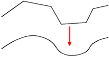
Converting Polyline to smoothed Spline
The command can be executed on many Polylines simultaneously. Select Polylines via filters.
At the end of the command, you're informed about how many Polylines were processed.
Spline vs Arc Conversion:
P2S creates true Spline objects (NURBS curves) while P2A creates arc segments. Splines are mathematically smoother but may be less compatible with some manufacturing processes.
Polyline to Lines P2L
Redraw Polyline with straight line segments.
Convert curved or smoothed Polylines back to straight line segments.
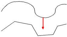
Converting curved Polyline back to straight segments
The command can be executed on many Polylines simultaneously. Select Polylines via filters.
At the end of the command, you're informed about how many Polylines were processed.
When to Use:
- Preparing geometry for systems that don't support curves
- Simplifying complex curves for analysis
- Reverting from P2A or P2S conversions
Show Polyline Smoothing PSP
Display both original Polylines and smoothing results where P2S command was executed.
Show the original Polylines and the smoothing results on Polylines where the P2S command has been applied.
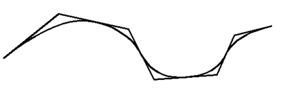
Displaying both original and smoothed Polylines
This allows visual comparison between the original geometry and the smoothed version.
Design Review:
Use PSP during design review to evaluate whether smoothing has preserved important geometric features or introduced unwanted changes.
Hide Polyline Smoothing PHP
Hide original Polylines and show only smoothing results where P2S command was executed.
Hide the original Polylines and display only the smoothing results on Polylines where the P2S command has been applied.
Note: Polylines that are smoothed can be returned to original form with the P2L command.
Workflow:
- Use P2S to smooth Polylines
- Use PSP to compare original and smoothed versions
- Use PHP to hide originals when satisfied with smoothing
- Use P2L to revert if needed
Add Polyline Vertices ADDPP
Add vertices to LwPolylines by selecting points anywhere on screen.
Select any point on screen which is added between the closest vertices of an LwPolyline while keeping it as a single entity.

Adding vertices to a Polyline
If you have drawn POLYLINE (old style), you must first run AutoCAD's CONVERTPOLY to convert to LWPOLYLINE. To draw LwPolylines by default, set PLINETYPE to 1.
LwPolyline vs Polyline:
LwPolylines (lightweight polylines) are more efficient and recommended for most 2D work. ADDPP works only with LwPolylines.
Delete Polyline Vertices DELPP
Delete vertices from LwPolylines by selecting points near vertices.
Select any point on screen and the closest vertex of an LwPolyline near that point is removed.

Deleting vertices from a Polyline
This command simplifies Polylines by removing unnecessary vertices while maintaining the overall shape.
Simplification Strategy:
Use DELPP to reduce file size and improve performance when Polylines have more vertices than needed for their intended purpose.
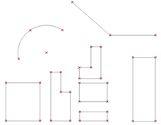
Extract Points from Line, 2D Pline, Arc, Spline ZXGPT
Export points from linear objects to text or Excel files.
What Gets Exported:
- Lines: Start and end points
- Pline: All vertices
- Arc: Start and end points, center point, and midpoint
- Spline: All Fit Points
Point extraction options and file selection
The command executes on many objects simultaneously. Select objects via filters.
As export file you can choose any text file or Excel. You have the ability to assign codes and numbering to exported points.
Exported points are unique - no duplicate points.
Note:
You can import these points into the Drawing as Blocks using the ITAX command.
Kilometric Positions on Polyline ZZXTH
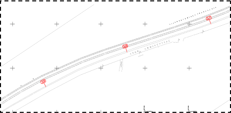
Insert Block at kilometric positions along a selected Polyline.
Insert Blocks marking kilometric positions along a selected Polyline. The Block size is set automatically according to the print scale.
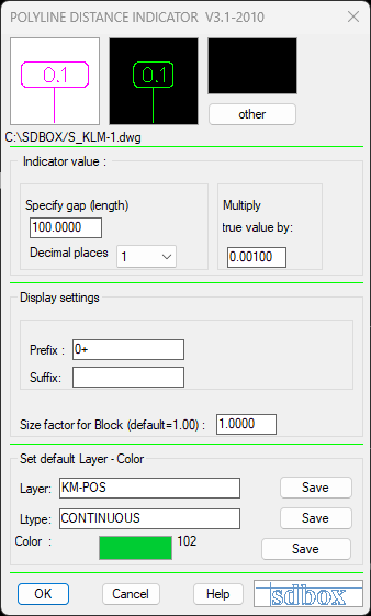
Placing kilometric markers along a Polyline
Configuration options for kilometric positioning
Typical Applications:
- Road and railway kilometer markers
- Pipeline stationing
- Cable run measurements
- Survey traverse stations
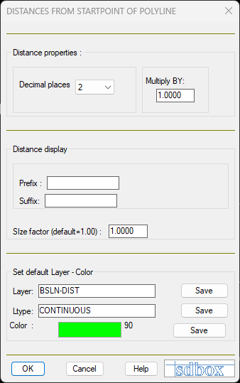
Distances from Start of Polyline ZZAPF
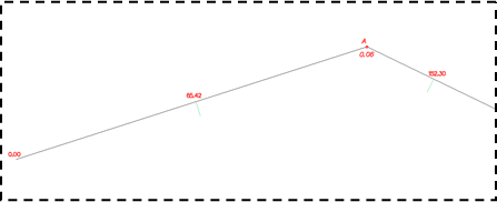
Insert distances from Polyline start at selected points along it.
Insert distances from the start of a Polyline at selected points along it. Distances can be written as text at selected positions or entered into a Block Attribute.
The text height is set automatically according to the print scale.
Measuring distances from Polyline start
Configuration options for distance annotation
Chainage Annotation:
This is essential for civil engineering and surveying work where stations along alignments need to be clearly marked with their distance from a starting point.
Line Types Legend ZYPGR
Create a legend of line types from selected linear objects in the drawing.
Creates a list on screen (in legend form) showing various line types you have selected based on Linetype, Scale, Layer, Color, etc., with explanation for each distinct type: Line, Pline, Mline, Xline, Ray, Spline, Arc, Circle, Ellipse, 3D Face, and Region in the drawing.
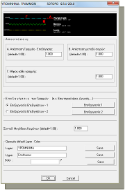
Line types legend created with ZYPGR
Detailed documentation for ZYPGR command
Comprehensive Tool:
The ZYPGR command is part of a suite of line management tools including ZVFE (configuration), ZYPGR1/ZYPGR2 (editing), ZGRLIST (line type list), and ZGRLS (detailed line list).