CAD Image Management Tools
SDBox Design Software - Command guide for image handling, georeferencing, and management in CAD drawings
Copy Selected Images to Directory ZCCIM
Copies selected images from the drawing to a directory of your choice.
Images that you select in the Drawing are copied to the destination folder you specify. (Note: This command works over networks as well.)
Usage
This command is typically used when you need to deliver a drawing that contains images located in various folders, and you want them all moved to the same folder.
Once you copy them to your chosen folder, you can set your drawing to read them from there using the following command ZCIMD.
Tip:
When you are prompted via the Windows dialog to specify the new directory, do not select a specific image or other file—simply browse to the desired folder and click Save, and the path will be set.
Select the images you want from the drawing screen using filters:

Select images using filters
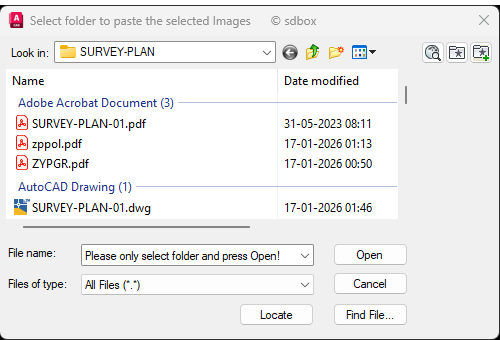
Folder selection interface
Note:
At the end of the command, you are informed how many images were copied. If some images are not found in the folder you specified, nothing changes for those.
Change Path of Selected Images ZCIMD
Change the search path for images in case the drawing cannot read them, or if you want them to be read from elsewhere.
Select which images will participate and simply indicate the new directory via a Windows dialog.
Usage
Select the images you want from the drawing screen using filters:
Select images using filters
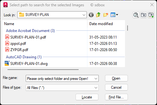
Change image path dialog
Note:
When prompted via the Windows dialog to specify the new directory, do not select a specific image or other file—simply browse to the desired folder and click Save, and the path will be set.
Images that are not found in the new directory remain unchanged. At the end of the command, you are informed how many were found and had their path changed.
^ Back to topIsolate/Reveal Selected Images ZFIM
When a drawing has a large number of images, use this command to isolate or reveal specific images to lighten the drawing.
Usage
Select on the drawing screen which images should remain visible; those not selected receive the property "Don't Show Image".
This command is typically used to lighten the drawing when it contains many images, or to toggle visibility of images through on-screen selections rather than through AutoCAD's dialog.
If you want to reveal all images again, type "All" when prompted to select which images the command should affect.
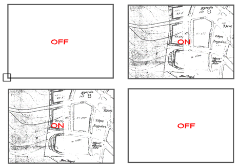
Image isolation interface
^ Back to topInsert Image with Auto-naming ZIMIN
Inserts an image of your choice and automatically creates layers ''tiff_prsrm_****'' for images intended for background adjustment, and ''tiff_apsp_****'' for images that will be placed in the drawing as excerpts.
Steps
- Select the image you want to insert. (If you have a grayscale image, it is recommended to convert it to black and white before insertion, so that it is "lighter" in the drawing and can have transparency.)
- You are asked if the inserted image is black and white. (If it is black and white, the created layer will have color 251, which is dark and helps differentiate from other drawing objects. If it is colored, the layer will be white.)
- You are asked if you want to create a layer for later placement of the image as an excerpt in the drawing.
Layer Naming Convention
The command is designed based on the fact that most images inserted in topographic work are used in boundary or line studies. Therefore, the created layer has the prefix "tiff_prsrm_****", where "prsrm" is an abbreviation for adjustment.
After it is adjusted behind the drawing, it may also be used as an excerpt, so you should move it to the layer "tiff_apsp_****", where "apsp" stands for excerpt. (Color 252 is set for mid-gray tone, ideal for printing black and white excerpts.)
This insertion and organization method groups adjustment images and excerpt images together, while the prefix "tiff_" groups all images.
Tip:
The created layers have the image name as a suffix. Therefore, before insertion, it is recommended to name your images meaningfully, e.g.: RYMO_FEK153D-89, GYS_6456-8, DE_55-2002, Topo_1999, KATOPSH_Adeia_340-2001, DK_340-2001, etc., so that when inserted into the drawing, the layers automatically receive corresponding names.
Transfer Objects Between Images ZIMAA
Select a source and a target image, and the objects that will be moved or copied from the source to the target.
Usage
The copy or transfer is based on the difference in position, size, and rotation between the target and the source.
This command was designed for transferring parcel boundaries to drawing excerpts, since images used as excerpts are often also placed behind the drawing for verification or boundary determination.
Example Workflow
- Copy the image to the corresponding excerpt layer.
- Bring the excerpt image to its print dimensions with the command ZDFS.
- Isolate the adjustment image, the excerpt image, and the parcel boundaries with the command ZF.
- Run ZIMAA where you select the adjustment image (as source), the excerpt image (as target), and the boundaries to be transferred.
- Use ZONELAY to move all location lines (usually boundary or subdivision lines) to the "YPOMNHMA" layer, so that no objects remain outside the main drawing on layers such as property boundaries.
- Hatch the parcel in the excerpt with the command HHA.
Insert Image with Georeference ZIMGEO
Insert an image with automatic placement, scale, and rotation based on the accompanying georeference file.
Usage
Select the image for insertion into the drawing, and a georeference file with the same name is automatically searched for. If found, the image is georeferenced upon insertion.
Supported georeference file extensions: t2w, tfw, tifw, tiw, j2w, jpgw, bmw, b2w, giw, g2w, wld
New Additions:
New features for inserting orthophotos from predefined addresses: Geotiffs and Map tiles.

Select Image for Georeferencing ZIMGS
Select an image on the screen and automatically place, scale, and rotate it based on its accompanying georeference file.
Usage
Select the image on the drawing screen, and a georeference file with the same name is automatically searched for. If found, the image is georeferenced.
Supported georeference file extensions: t2w, tfw, tifw, tiw, j2w, jpgw, bmw, b2w, giw, g2w, wld
^ Back to topFit Contour with Real Sides ZIMDD
Select a continuous contour on the image, give the real value of each side, and the image "comes" to its real dimensions by calculating the average scaling, translation, and rotation.
Detailed Steps
- Give 2 points on the image for the first side.
- Enter or type the real dimension of that side.
- Give the next point for the 2nd (continuous) side.
- Enter or type the real dimension of that side.
- Continue for as many sides as you want.
- Select the objects that will be fitted to the above data (you can select more than one image or other objects).
- The image or whatever you selected "comes" to its real dimensions.
- Optionally, a Polyline can be drawn representing the exact shape, position, direction, and length of the sides as you specified.
Note:
The contour you give does not need to be closed. Usually, the largest continuous contour where dimensions are visible or known is selected.
Label Image Names ZIMNM
Automatically writes the names of selected images in the upper left corner of each image.
Detailed Steps
- Give the text height by number or on-screen dimension.
- Select as many images as you want.
- The name of each image is automatically written in the upper left corner (on the layer of each image).
Tip:
It is recommended to choose a large text height so that in a drawing with many images you can distinguish the names from a distance.