CAD Blocks Management
SDBox Design Software - Command guide for insertion, editing and management of Blocks in CAD drawings
Insert Fixed Dimension Symbols ASD
Insertion of symbols (Blocks) from a Library in the dimensions they were designed. You can enrich the library with your own Blocks.
Selection of Block from a symbols library for insertion in the drawing screen with point and rotation angle.
These symbols are inserted into the Drawing exactly as they were designed (regardless of the print scale of the Drawing they are inserted into) and are usually architectural symbols for Plan, Section and Elevation.
You can enrich the library with your own symbols and use them easily in any Drawing.
You can set the symbols library to be read from a shared folder on a network so that many users can use and enrich the same library.
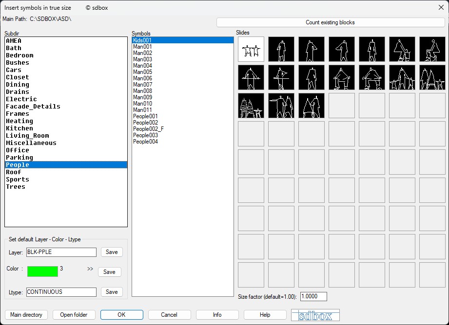
ASD command interface for block selection
Subdirectory
This list shows the names of the subfolders contained in the ASD folder.
Each subfolder constitutes a different category of symbols and contains Drawings (*.dwg) that are the symbols.
When you select a category, the adjacent lists "Symbols" and "Slides" display the names of the Drawings contained in the selected subfolder-category.
You can create new folders via Windows inside the ASD folder to contain Drawings (*.dwg) for insertion into the Drawing as symbols.
Symbols
This list shows the Drawings (*.dwg) contained in the selected subfolder-category from the "Subdirectory" list.
From this list you can select the symbol to be inserted into the Drawing.
When you click on a Drawing, the corresponding Slide becomes highlighted in the adjacent "Slides" list.
With a double-click you are automatically transferred to the drawing screen for insertion of the selected Symbol.
Slides
This list shows the corresponding Slides (*.sld) contained in the selected subfolder-category from the "Subdirectory" list.
When you create a new Drawing-symbol in a subfolder, create also the corresponding Slide of the symbol, with the AutoCAD mslide command, giving it the same name as the symbol.
For Drawings-symbols that do not have slides, the indication "No Slide" appears in the corresponding position.
General Directory
The command ends (no symbol is inserted) and opens the ASD folder containing the subfolders-categories of symbols.
In the ASD folder you can create new subfolders-categories with Drawings that will be inserted as symbols with the command.
You can open this folder also outside the command with the ASDDIR command.
Open Folder
The command ends (no symbol is inserted) and opens the subfolder-category you have selected in the "Subdirectory" list and displayed in the "Symbols" list.
The folder that opens contains the drawings-symbols (*.dwg) and the corresponding Slides.
You can rename a Drawing or create a new one.
When you rename a Drawing, rename also the corresponding Slide.
When you create a new Drawing, create also the corresponding Slide with the AutoCAD mslide command.
Enter Layer for Block insertion:
Pick insertion point for Block:
Enter rotation angle <0.00>:
Notes:
When you create a new Drawing-symbol you can set the insertion point with the AutoCAD base command.
Each subfolder can contain a maximum of 63 Drawings.
If you have more Drawings in a category, you can create a new subfolder (with name **-2) to contain them.
Command Usage:
The selections you make each time with the ASD command are saved and suggested from then on when you run the command again in the same Drawing or in any other.
If you agree with what is suggested (as the last selection) when opening the tab, you can press Enter or Space to accept them and continue with symbol insertion in the Drawing screen.
Tips:
You can create as many subfolders-categories as you want.
The ASD command reads only drawings that exist in subfolders of the ASD folder.
Plain drawings that exist inside the ASD folder cannot participate in the command.
The command name ASD is an abbreviation of "Architectural Symbols into the Drawing".
Change Directory for Fixed Dimension Symbols ASDCHDIR
Definition of the Directory where the folders with fixed dimension Blocks are located. This Directory is read by the command and opens a tab with the Blocks for insertion. The Directory can also be network.
You define a new address for the ASD folder containing the subfolders-categories of fixed dimension symbols.
You can set the symbols library (ASD folder) to be read from a shared folder on a network so that many users can use and enrich the same library.
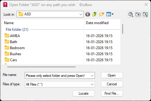
Dialog for changing the ASD library directory
To change the address of the ASD library you simply need to open (with the above window) the ASD folder in whichever address you have placed it.
Once you open the folder, without selecting anything else with the mouse, and press Save, the address is recorded and this is set as the library address used by the ASD command.
In the File Name position is written "Do not change anything here!" to remind you that after opening the ASD folder you do not need to select any file or anything else, just press Save.
Tips:
You can change the ASD address as many times as you want and within the same Drawing.
The general ASD folder can have another name of your preference.
You can open the ASD folder with the ASDDIR command at any time in the Drawing.
Open Fixed Dimension Symbols Folder ASDDIR
Opening of the Directory containing the folders with fixed dimension Blocks. You can with new folders shape the categories or copy new Blocks.
When you type ASDDIR in the drawing, the folder (General Directory) that is defined as the library of subfolders-categories for the ASD command opens (via windows).
In the folder that opens you can create new subfolders where to transfer or create new drawings and slides.
Notes:
In the folder that opens you can transfer or create new folders of your own with drawings and slides which will automatically participate in the ASD command.
Command Usage:
Apart from creating or transferring new subfolders, drawings and slides, you can use the ASDDIR command to have an overview or confirm the address used by the ASD command.
Insert with Directory Selection ASDA
Insertion of symbols (Blocks) in the dimensions they were designed. The selection is made from a Windows window and you can select any drawing for insertion.
Selection of Block from any address of the computer or network for insertion in the drawing screen with point and rotation angle.
These symbols are inserted into the Drawing exactly as they were designed (regardless of the print scale of the Drawing they are inserted into).
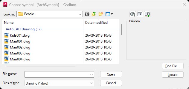
File selection dialog for ASDA command
Notes:
When you create a new Drawing-symbol you can set the insertion point with the AutoCAD base command.
Command Usage:
The file address you choose to insert into the drawing as a symbol with the ASDA command is saved and suggested from then on when you run the command again in the same Drawing or in any other.
Tips:
You can insert a symbol into the Drawing from any address of your preference.
The ASDA command is not related to the fixed dimension symbols library address of the ASD command.
The command name ASDA is an abbreviation of "Architectural Symbols into the Drawing from Any directory".
Open Folder of Last Used ASD Block ASDADIR
Opening of the folder containing the fixed dimension Block that was last inserted with the ASDA command.
When you type ASDADIR in the drawing, the folder containing the Symbol (*.dwg) that was selected the last time in any drawing for insertion with the ASDA command opens (via windows).
In the folder that opens you can create new subfolders where to transfer or create new drawings.
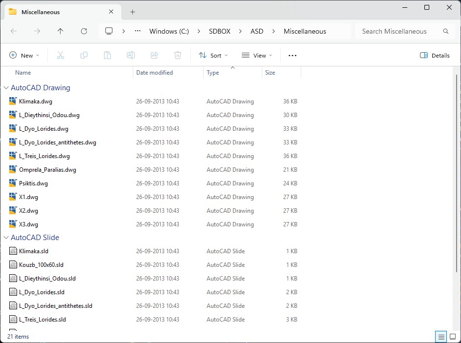
Folder opened by ASDADIR command
Notes:
Same as for the ASDA command.
Insert Scaled Symbols MBL
Insertion of symbols (Blocks) from a Library in size proportional to the print scale. You have the ability to type points, set rotation and insertion factor. You can enrich the library with your own Blocks.
Selection of Block from a symbols library for insertion in the drawing screen with point.
These symbols are inserted into the Drawing with size proportional to the print scale so that they print clearly.
You can enrich the library with your own symbols and use them easily in any Drawing.
You can set the symbols library to be read from a shared folder on a network so that many users can use and enrich the same library.
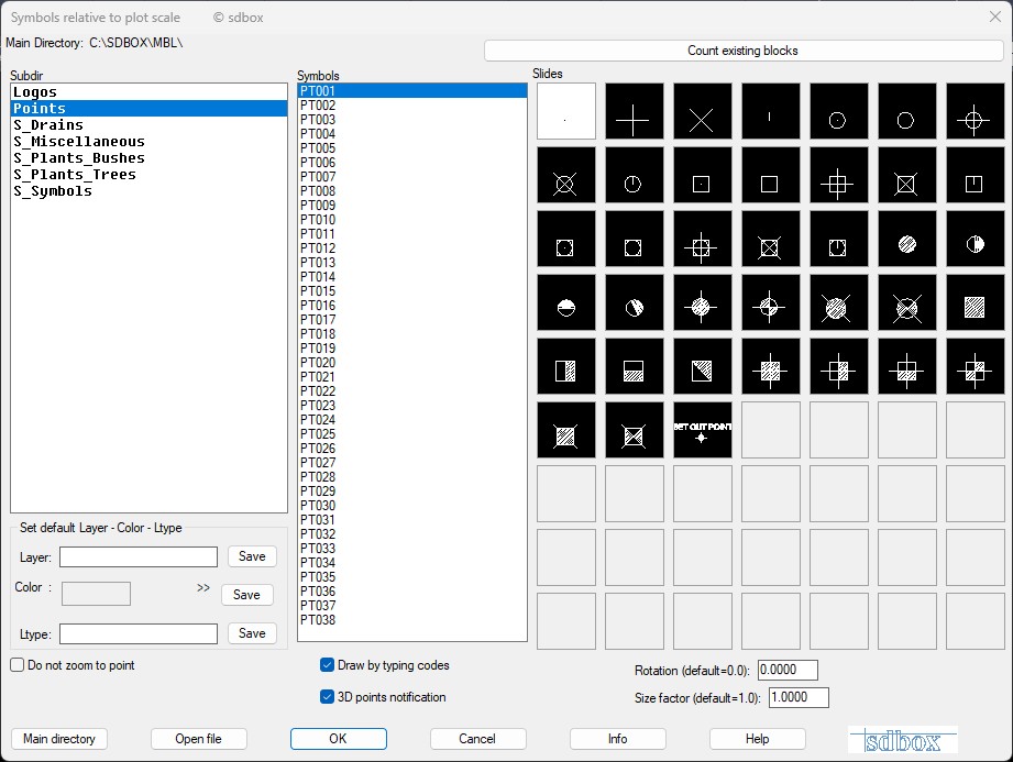
MBL command interface for scaled block insertion
Drawing with point typing
You can select the Blocks that will participate in the command and which Attribute contains the codes you will type during Drawing.
Update for 3D points
If you select this field then during drawing you will be notified when you select a point that does not have Z=0.00.
During drawing you have many possibilities for point construction.
Notes:
Regarding the rest of the tab, the same as for the above ASD command apply.
Change Directory for Scaled Symbols MBLCHDIR
Definition of the Directory where the folders with scaled Blocks are located. This Directory is read by the command and opens a tab with the Blocks for insertion. The Directory can also be network.
You define a new address for the MBL folder containing the subfolders-categories of symbols.
You can set the symbols library (MBL folder) to be read from a shared folder on a network so that many users can use and enrich the same library.
Notes:
Same as for the ASDCHDIR command.
Open Scaled Symbols Folder MBLDIR
Opening of the Directory containing the folders with scaled Blocks. You can with new folders shape the categories or copy new Blocks.
When you type MBLDIR in the drawing, the folder (General Directory) that is defined as the library of subfolders-categories for the MBL command opens (via windows).
In the folder that opens you can create new subfolders where to transfer or create new drawings and slides.
Notes:
Same as for the ASDDIR command.
Scaled Symbols with Directory Selection MBLA
Insertion of symbols (Blocks) in size proportional to the print scale. The selection is made from a Windows window and you can select any drawing for insertion.
Selection of Block from any address of the computer or network for insertion in the drawing screen with point and rotation angle.
These symbols are inserted into the Drawing with size proportional to the print scale so that they print clearly.
Notes:
Same as for the ASDA command.
Open Folder of Last Used MBL Block MBLADIR
Opening of the folder containing the scaled Block that was last inserted with the MBLA command.
When you type MBLADIR in the drawing, the folder containing the Symbol (*.dwg) that was selected the last time in any drawing for insertion with the MBLA command opens (via windows).
In the folder that opens you can create new subfolders where to transfer or create new drawings.
Notes:
Same as for the ASDADIR command.
Insert-Export Blocks with Sequential Names ZZB
Insertion of Block into the Drawing with simultaneous export to a file and multiple naming possibilities during insertion and drawing on the screen.
You have the ability to use the command from simple insertion of symbols with sequential numbering and fixed elements, up to complex use with export of the insertion coordinates to a file with predefined elements.
ZZB command interface part 1
Details link for coordinate export
Command Usage:
Used for systematic insertion of blocks with attributes that need to be recorded in external files for further processing.
Number in Circle NNAR
Placement of Circle Block with number with sequential numbering.
Automatic numbering during the command and ability to select the increment units of the numbering.
You insert the Block, a number is given and you move it to its final position.
With NNARR you also have the ability to rotate the Block.
The size of the Blocks is set automatically according to the print scale.
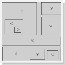
Example of numbered circles
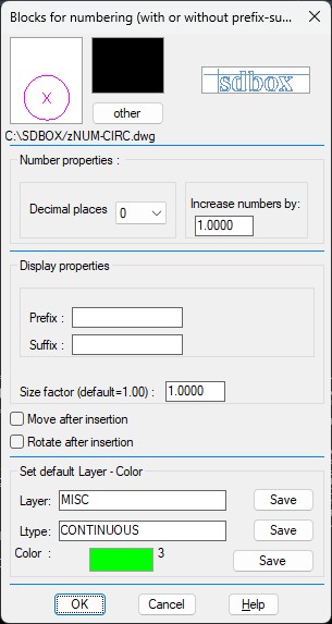
NNAR command dialog
Notes:
If you want to insert a Block with simple or complex alphanumeric phrases in a circle, square or rhombus then use the ZZB command.
In case you have already inserted a Block with the command and want to add some number to all (or perform any operation) use the ZNMB command.
Command Usage:
You can set as large numbers as you want. The command is designed so that any number always fits inside the circle.
Insert Circle Symbol ZKYK
Insertion of Block in a circle with size proportional to the print scale and with selection from a library. In the library you can also set explanations for each Block.
Selection of Block from a symbols library for insertion in the drawing screen.
These symbols are inserted into the Drawing with size proportional to the print scale so that they print clearly.
You can enrich the library with your own symbols and use them easily in any Drawing as for each Block you can give a description to remind you of its use.
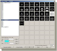
ZKYK command details interface
^ Back to topInsert Symbol in Plate ZTET
Insertion of Block in a plate with size proportional to the print scale and with selection from a library. In the library you can also set explanations for each Block.
Selection of Block from a symbols library for insertion in the drawing screen.
These symbols are inserted into the Drawing with size proportional to the print scale so that they print clearly.
You can enrich the library with your own symbols and use them easily in any Drawing as for each Block you can give a description to remind you of its use.

ZTET command details interface
^ Back to topInsert North or Arrow Symbol ZBOR
Insertion of North or arrow Block in the drawing screen with size proportional to the print scale and with selection from a library.
Selection of Block from a symbols library for insertion in the drawing screen.
These symbols are inserted into the Drawing with size proportional to the print scale so that they print clearly.
You can enrich the library with your own symbols and use them easily in any Drawing as for each Block you can give a description to remind you of its use.
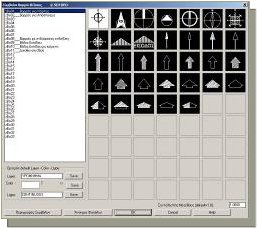
ZBOR command details interface
^ Back to topCount Block-Xref ZBLK
Opens a file that includes the Blocks and Xrefs that exist in the Drawing with their count.
The command counts all the Blocks or Xrefs that exist in the Drawing and displays them in the file "KATAMETHRHSH_BLOCK_SXEDIOY.zblk" sorted by name and with a number corresponding to how many times each exists in the Drawing.
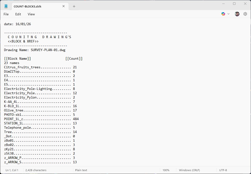
Example of block counting output
For Blocks that show the number 0 (count) it means that this Block was once inserted into the Drawing, has been deleted and has remained as an entity in the AutoCAD library so that it can be reinserted if needed.
Notes:
The command can be used as many times as you want in the Drawing.
Each time it opens, and in each drawing it opens the same file "SDBOX\KATAMETHRHSH_BLOCK_SXEDIOY.zblk".
If you want you can save it (Save As) to an address of your choice with another name for any use of yours.
Command Usage:
- To have an image of which and how many Blocks exist in the Drawing.
- If a Block exists in the Drawing.
- If you want to copy the name of a Block for use in another command.
Tips:
If after opening the file you save it (Save As) to an address of your choice then the information at the beginning of the file reminds you when and from which Drawing the file originated.
Symbols Legend ZYPBL
Legend of which types of Block are selected from the Drawing.
A List is created on screen (in legend form) where the various types of Block that you have selected are displayed according to Block Name, size, Layer, Color etc. and explanation for each Block.
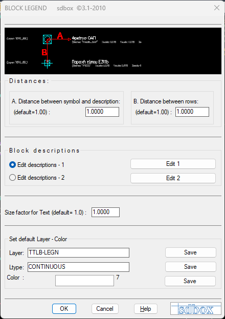
ZYPBL command details interface
^ Back to topEdit Attribute in Block ZZATT
Editing of Attribute contents in Block. Conversion to Uppercase or lowercase, addition of phrases at the beginning or end, change of phrases, changes to Color, Layer or TextStyle.
The command is executed simultaneously on the desired Attributes of the selected Blocks.
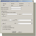
ZZATT command details interface
^ Back to topChange Tag Name ZZTAG
Editing of Attribute names (TAG) in Block. Conversion to Uppercase or lowercase, addition of phrases at the beginning or end, change of phrases.
This command is useful when you want to change the names of the Attributes in some Block so that you can handle them later collectively.
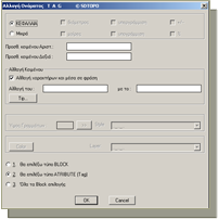
ZZTAG command example
For the use of the command the same as for the above ZZATT command apply with the difference that some fields are disabled.
^ Back to topChange Block Texts DDE
Editing of contents, Texts (Text, Mtext), Attributes of a Block, dimension values (Dimensions) and Rtext.
The command was originally created for Acad 2000 with the aim of being the same command that edits Text contents, Block and Dimension.
Details
^ Back to topMatch Block Scale ZMSB
You select the Block that has the desired X, Y, Z Scale and then the Blocks that you want to acquire the same Scale.
This command is often used when same type Blocks have been inserted into the Drawing with different sizes. Once they all acquire the same size you can use them collectively in other commands.
Note: When asked to select the Block with the desired X, Y, Z Scale you can instead of selecting a Block simply type a number which will be transferred to all 3 scales.
^ Back to topBlock Table ZPBL
A table is drawn on screen in whose columns the contents of selected Attributes and the coordinates of the Blocks you select are displayed.
The process is the same in the various versions of the command and the only difference is in the suggested Blocks that are selected, the Attributes that are recorded and the title of the Table, which are saved and suggested in each new use per version.
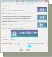
ZPBL command details interface
^ Back to topExport Block ZXBL
Block elements are exported to a file where each row contains the contents of the desired Attributes and the coordinates of the Blocks you select.
The process is the same in the various versions of the command and the only difference is in the suggested Blocks that are selected, the Attributes that are recorded and the file, which are saved and suggested in each new use per version.
Details
^ Back to topCopy Xref to Folder ZCCXR
The drawings that exist as Xref in the present Drawing are copied to a Directory of your choice. (Note: The command works also on networks.)
This command is usually used, among others, when you want to deliver a drawing that has Xrefs located in various Directories and these to be transferred to the same folder.
Once you copy them to the folder of your choice you can set your drawing to read them from there with the following command ZCXRD.
Note:
When, via the Windows window, you are asked to indicate the new Directory, do not select a specific Drawing or other file, just press Save and the address will be set.
Change Xref Search Directory ZCXRD
If you want to change the search Directory of Xrefs, in case the Drawing does not read them or in case you want them to be read from elsewhere, you select which of the Xrefs will participate and you simply indicate the new Directory via a Windows window.
Select in the drawing screen based on filters the Xrefs you desire:

Filter-based selection interface
Xrefs that are not found in the new Directory, nothing changes for them.
Anyway at the end of the command you are informed about how many were found and changed Directory.
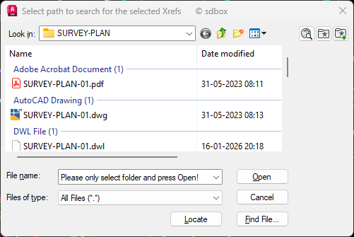
ZCXRD command dialog
Note:
When, via the Windows window, you are asked to indicate the new Directory, do not select a specific Drawing or other file, just press Save and the address will be set.
Hide - Show Xref ZFXR
Unload and Reload Xref with their selection in the drawing screen.
You select in the drawing screen which Xrefs will remain and those you did not select become Unload.
Usually the command is used to lighten the Drawing when it has many Xrefs or to show and hide alternately the Xrefs with selections on screen and not from the AutoCAD window.
^ Back to top